SHT31 ARDUINO GUIDE · SAMPLING AND ALERT
SHT31 on Arduino: Single-Shot vs Periodic Mode and ALERT
Use SHT31 single-shot mode when the controller needs an occasional temperature and humidity reading. HT3x-DIS is the next generation of Sensirion’s temperature and humidity sensors. It builds on a new CMOSens® sensor chip that is at the heart of Sensirion’s new humidity and temperature platform. The SHT3x-DIS has increased intelligence, reliability and improved accuracy specifications compared to its predecessor. Use periodic mode for a fixed sampling rate or the sensor's ALERT threshold output. On an Arduino Uno, verify the I²C address and one valid reading before configuring either feature.
SHT31 single-shot or periodic mode: which should you choose?
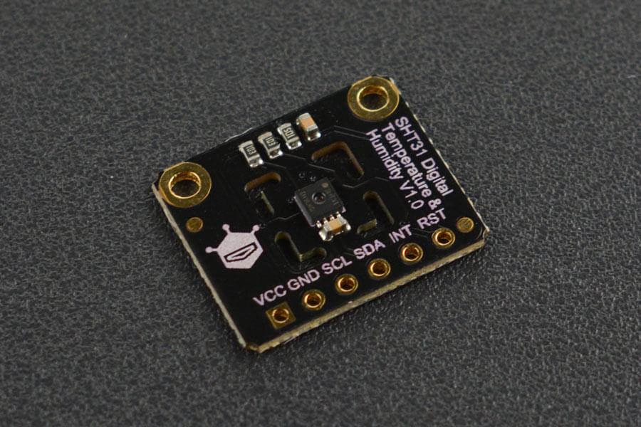
SHT31 single-shot mode starts one measurement on command and then returns to idle. Periodic mode collects measurements at the selected 0.5, 1, 2, 4 or 10 Hz rate; the SEN0331 ALERT threshold example uses this mode. Choose by the required update rate and alarm behavior, then verify the returned error status before using any value.
Which SHT31 breakout and pins does this guide cover?
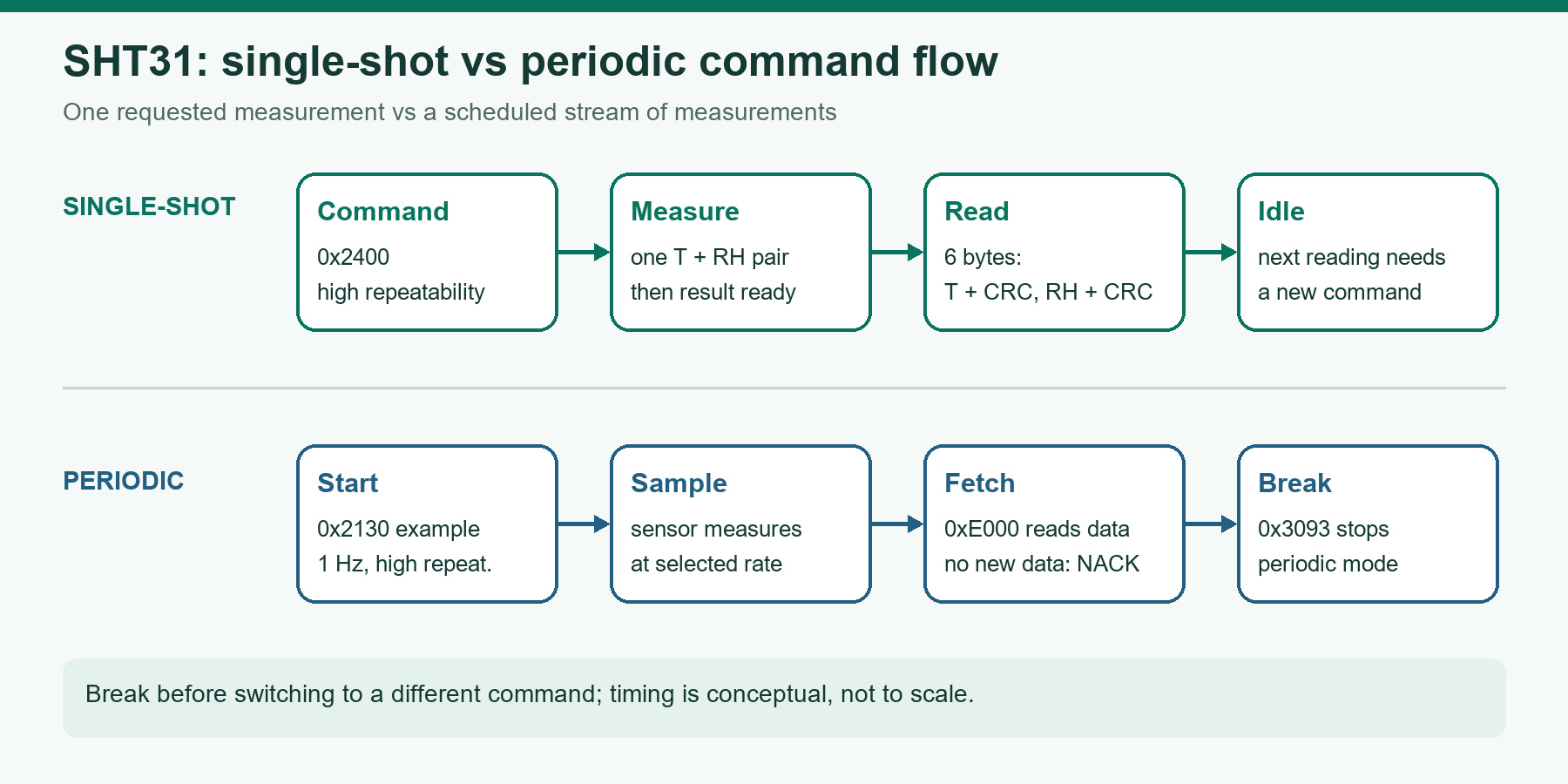
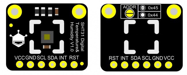
This guide covers the DFRobot SEN0331 SHT31 breakout. Its VCC, GND, SCL, SDA, INT and RST labels describe this board, not every SHT31 module. The source drawing gives a board outline of about 19 × 16 mm and 15 mm mounting-hole pitch. Check the current drawing before designing a PCB or enclosure.
How should you read the SHT31 accuracy curves?
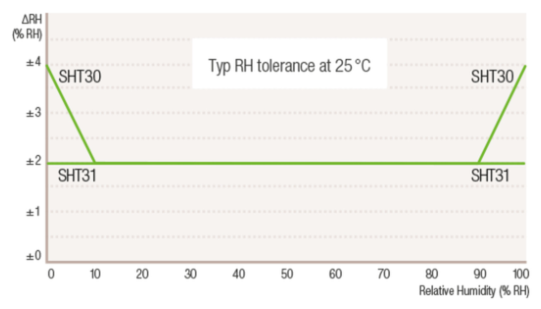
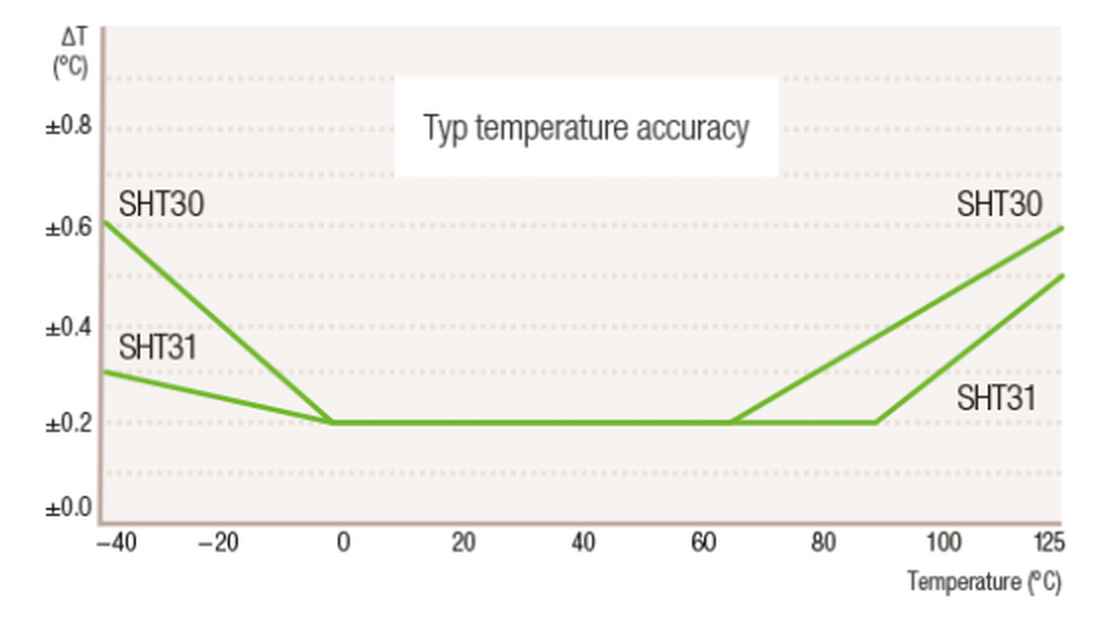
The source comparison plots show typical chip-level tolerance, not the error of an assembled Arduino measurement. At 25 °C, the SHT31 relative-humidity curve is ±2 %RH across the plotted humidity range. The temperature curve shows ±0.2 °C over approximately 0–90 °C, with wider typical tolerance outside that interval. SHT30 appears in both plots for context; this guide uses the SHT31.
How do you wire the SEN0331 SHT31 to Arduino Uno?
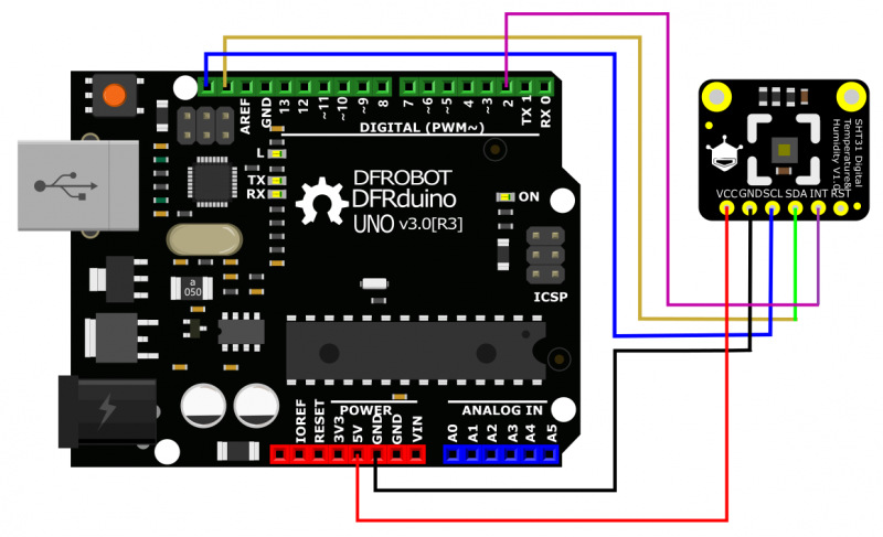
For the DFRobot SEN0331 and Arduino Uno example, connect VCC to 5 V, GND to GND, SDA to A4 and SCL to A5. The source drawing also wires INT and RST for later exercises; neither is needed to confirm the first I²C temperature/humidity reading. On another controller or breakout, check the board's supply and pull-up voltages before copying the Uno connection.
Sensirion specifies 0x44 when the SHT31 ADDR pin is low and 0x45 when it is high; 0x44 is the chip-level default. The DFRobot_SHT3x constructor defaults to 0x45. A breakout can fix the ADDR state, so scan the assembled board and pass the observed address to the library. If neither address responds, check power, ground, SDA/SCL order, pull-ups and voltage before changing measurement code.
How do you get a valid SHT31 single-shot reading?
Install the DFRobot_SHT3x Arduino library, select Arduino Uno and its serial port, then open Serial Monitor at 9600 baud. This complete first-reading sketch probes 0x44 and 0x45, stops if neither or both respond, initializes the sensor, and records each measurement with a timestamp and a validity status. It uses the DFRobot library to request a high-repeatability single-shot measurement and check the returned error field.
#include <Wire.h>
#include <DFRobot_SHT3x.h>
#include <math.h>

// SEN0331 example: connect SDA to A4, SCL to A5, and RST to D4.
DFRobot_SHT3x sensor44(&Wire, 0x44, 4);
DFRobot_SHT3x sensor45(&Wire, 0x45, 4);
DFRobot_SHT3x *sensor = nullptr;
uint8_t sensorAddress = 0;
unsigned long sampleNumber = 0;

bool addressResponds(uint8_t address) {
  Wire.beginTransmission(address);
  return Wire.endTransmission() == 0;
}

void haltWithMessage(const char *message) {
  Serial.println(message);
  while (true) delay(1000);
}

void setup() {
  Serial.begin(9600);
  Wire.begin();
  delay(100);

  const bool found44 = addressResponds(0x44);
  const bool found45 = addressResponds(0x45);
  if (!found44 && !found45) {
    haltWithMessage("No device at 0x44 or 0x45; check power and SDA/SCL");
  }
  if (found44 && found45) {
    haltWithMessage("Both addresses respond; isolate one module for this test");
  }

  sensorAddress = found45 ? 0x45 : 0x44;
  sensor = found45 ? &sensor45 : &sensor44;
  if (sensor->begin() != 0) {
    haltWithMessage("I2C ACK received, but SHT31 initialization failed");
  }

  Serial.print("SHT31 ready at 0x");
  Serial.println(sensorAddress, HEX);
  Serial.println("sample,ms,address,temp_c,rh_percent,status,error");
}

void loop() {
  const unsigned long startedMs = millis();
  DFRobot_SHT3x::sRHAndTemp_t reading =
      sensor->readTemperatureAndHumidity(sensor->eRepeatability_High);
  ++sampleNumber;

  Serial.print(sampleNumber);
  Serial.print(',');
  Serial.print(startedMs);
  Serial.print(",0x");
  Serial.print(sensorAddress, HEX);
  Serial.print(',');

  const bool valid = reading.ERR == 0 &&
      !isnan(reading.TemperatureC) && !isnan(reading.Humidity) &&
      reading.TemperatureC >= -40.0 && reading.TemperatureC <= 125.0 &&
      reading.Humidity >= 0.0 && reading.Humidity <= 100.0;
  if (valid) {
    Serial.print(reading.TemperatureC, 2);
    Serial.print(',');
    Serial.print(reading.Humidity, 2);
    Serial.println(",ok,0");
  } else {
    // Leave the data fields empty: a failed read is not a measurement.
    Serial.print(",,invalid,");
    Serial.println(reading.ERR);
  }
  delay(1000);
}
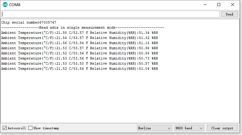
A successful row ends in ok,0 and contains temperature and RH in the same sample. An invalid row leaves both value fields blank; the last field reports the library error code. The library sends the single-shot command, waits for conversion, reads six bytes, and checks the separate temperature and humidity CRC bytes. A probe ACK only shows that an I²C device responded, so initialization and the measurement status must also pass. The ms field is Arduino uptime, not a wall-clock timestamp.
A usable row contains both temperature and relative humidity with no read error. Record the two values together after the module has stabilized: nearby heat or direct breath can change local temperature and shift the RH reading. Plausible serial values show that a measurement was returned; they do not establish sensor accuracy without an independent reference.
When should the SHT31 use periodic measurement mode?
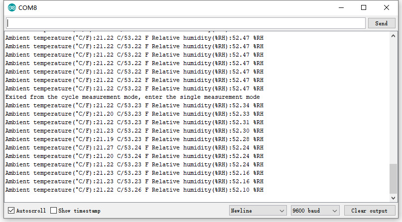
Use SHT31 periodic mode when the application needs a regular measurement stream. The sensor supports 0.5, 1, 2, 4 and 10 measurements per second. Each Fetch Data command (0xE000) obtains an available pair; if there is no new data, the sensor NACKs the read header. Polling faster does not create another measurement. At the highest rate, the datasheet cautions that sensor self-heating may occur.
The DFRobot library example starts a 1 Hz stream with startPeriodicMode(eMeasureFreq_1Hz). Before sending an unrelated sensor command, stop periodic acquisition with stopPeriodicMode(); the underlying Break command is 0x3093 and returns the sensor to single-shot mode. Record this transition so later readings can be matched to the mode that produced them.
Why is the SHT31 ALERT pin not responding?
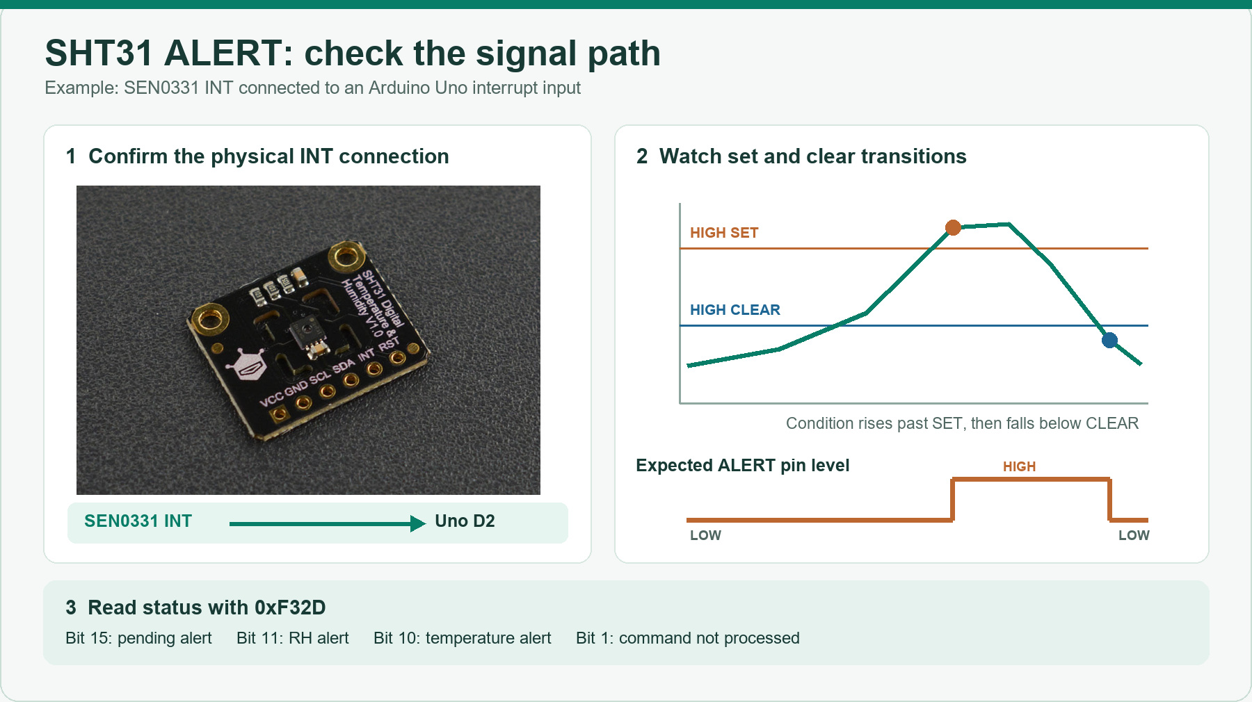
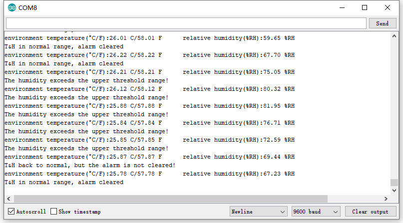
In the SEN0331 example, the SHT31 ALERT threshold output is used in periodic mode. Set upper and lower trip points and separate clear points, then connect INT to an interrupt-capable host pin. The gap between trip and clear points provides hysteresis, so small fluctuations around a limit do not repeatedly toggle the alarm.
If INT does not change, confirm periodic mode first, then read back the configured limits and check the physical pin level as conditions cross each trip and clear point. Timestamp both measurements and interrupt events. A printed alarm message alone does not verify the electrical signal path.
For raw-command debugging, status-register read command 0xF32D distinguishes several failure paths: bit 15 reports a pending alert, bit 11 a humidity tracking alert, bit 10 a temperature tracking alert, and bit 1 an unprocessed command. The ALERT output goes high when its programmed condition is met. If the output is unused, the datasheet says to leave it floating.
SHT31 not detected or reading incorrectly: what should you check?
| Observation | First check | Next decision |
|---|---|---|
| No I²C address appears | Power, ground, SDA/SCL order, pull-ups and voltage | Restore bus communication before changing sensor code |
| Scan finds 0x44 or 0x45; initialization fails | Configured library address and ADDR selection | Use the observed address and recheck the library instance |
| Read returns an error or implausible values | Error code, measurement mode, timing and local heat | Log temperature and RH together after stabilization |
| INT never changes | Periodic mode, limit settings, INT wiring and host interrupt pin | Check the physical pin and each threshold transition separately |
Technical sources
- DFRobot_SHT3x Arduino library, constructor, return fields and mode API.
- SHT31-to-FHT31 qualification guide for teams evaluating a separate sensor candidate.
The photographs and Serial Monitor screenshots are from the DFRobot SEN0331 tutorial; their readings are examples from that source, not NYFEA measurements. DFRobot and SHT31 identify third-party products. NYFEA is not affiliated with or endorsed by their owners.
Evaluating a sensor for a production design?
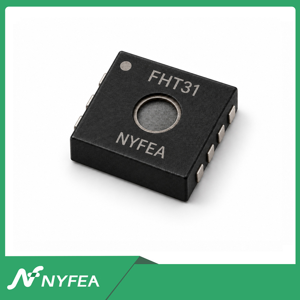
Once the SHT31 baseline works, compare the complete device requirements before considering a different sensor. Review NYFEA FHT31 product information and use the qualification guide to plan the necessary package, electrical, firmware and measurement checks.