SHT31 VS SHT40 · DIFFERENCES, I²C CODE, WIRING AND PCB
SHT31 vs SHT40: Key Differences, Code and PCB Compatibility
Thinking of replacing an SHT31 with an SHT40? Compare the design trade-offs, then use the ESP32 diagnostic sketch and pinout map to see exactly what your firmware and PCB would need.
DIRECT ANSWER
Can SHT40 replace SHT31?
No—not as a drop-in replacement. You can usually retain the host I²C peripheral, six-byte unpacking and two-word CRC-8 routine for the single-shot path shown here, but the measurement command, wait time, relative-humidity conversion and feature calls must be reviewed. A bare SHT40 cannot use the standard SHT31 land pattern because the packages differ in size and contact count. A four-wire breakout cable is reusable only when the actual pin order, supply path and SDA/SCL pull-up voltage are compatible. An address ACK or a passing CRC proves neither model identity nor finished-product compatibility. SHT3x-DIS datasheet; SHT4x datasheet.
SHT31 vs SHT40: what are the main differences?
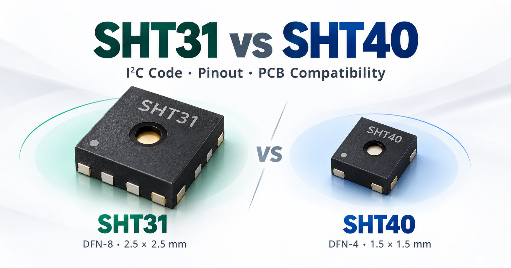
The fastest way to compare the two devices is to separate shared I²C mechanics from model-specific commands, conversion, package and features. The table below summarizes the high-repeatability single-shot path and the standard bare packages discussed in this guide.
| Item | SHT31 | SHT40 | Design impact |
|---|---|---|---|
| Standard bare package | 2.5 × 2.5 × 0.9 mm, eight contacts | 1.5 × 1.5 × 0.5 mm, four contacts | Bare-chip PCB footprint is not reusable as-is. |
| I²C address | 0x44 is the chip-level default; 0x45 can be selected with ADDR | Depends on the exact order code; SHT40-xD1B variants can use 0x44, 0x45 or 0x46 (for example, AD1B uses 0x44) | A matching ACK does not identify the model. |
| High-repeatability single-shot command | 0x24 0x00 | 0xFD | The old measurement command cannot simply be reused. |
| Measurement reply | Six bytes | Six bytes | The parser structure can be reused for this path after model verification. |
| CRC-8 | Polynomial 0x31, init 0xFF, per two-byte word | Same grouping and polynomial | The CRC routine is reusable; a passing CRC does not prove model identity. |
| Temperature conversion | −45 + 175 × rawT / 65535 | Same equation in this path | This conversion can be reused. |
| Relative-humidity conversion | 100 × rawRH / 65535 | −6 + 125 × rawRH / 65535 | The RH formula must change with the verified model. |
| Supply review | 2.15–5.5 V at the bare sensor | Standard SHT40 VDD is 1.08–3.6 V | Recheck sensor VDD and every SDA/SCL pull-up rail before migration. |
| ALERT / nRESET pins | Available on SHT31 | No matching pins on the standard four-pin SHT40 | Feature-level migration requires a separate design decision. |
For first-time bring-up rather than migration analysis, see the SHT31 Arduino guide and the SHT40 with ESP32 wiring and I²C code guide.
SHT31 vs SHT40 accuracy and power: is the change worthwhile?
Compare accuracy where your product will operate
At 25 °C and 50%RH, the published typical RH tolerances are ±2%RH for SHT31 and ±1.8%RH for SHT40. That 0.2-percentage-point difference is not a guaranteed improvement in your assembled product. Check each model's maximum-tolerance curve and temperature/RH map against your operating range. The headline temperature tolerance is ±0.2 °C for both, with conditions defined by their respective curves.
A useful acceptance question is: does either sensor exceed your allowed error at the temperatures and humidities that matter? Then check the installed assembly. A smaller nominal tolerance does not correct a warm PCB location or poor air exchange.
Compare the sampling schedule, not one current number
The SHT40 datasheet lists typical average currents of 0.4 µA in low-repeatability mode and 2.2 µA in high-repeatability mode at one measurement per second with the heater off. The sketch below uses high repeatability. Treating 0.4 µA as its current budget would mix operating modes.
For a battery design, compare both sensors at the same voltage, sampling interval and repeatability. Include heater duty, regulator loss, module LEDs and host wake time. Measure energy over a complete application cycle before claiming a battery-life gain. If the host radio dominates that cycle, changing the humidity sensor may have little effect on total runtime.
Why does an SHT40 answer at 0x44 while the old SHT31 code fails?
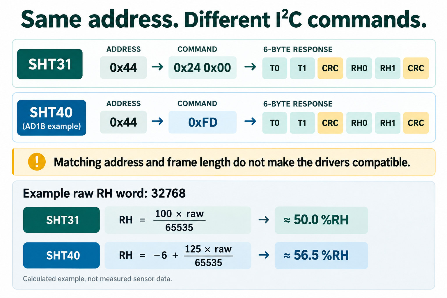
An I²C scan only establishes that a device acknowledges an address at that moment. For a high-repeatability single-shot measurement, the SHT31 takes the two-byte command 0x24 0x00, whereas an SHT40 with the appropriate order code takes the one-byte command 0xFD. Both return six bytes: a 16-bit temperature word, its CRC, a 16-bit humidity word and its CRC. Matching address and response length do not make the commands interchangeable. SHT3x-DIS command and data format; SHT4x quick-start and command table.
A wrong humidity formula can be harder to notice than a failed transaction. Take a hypothetical raw RH word of 32768, close to the midpoint of the 16-bit scale. The SHT31 equation, 100 × raw / 65535, gives approximately 50.0%RH. The SHT40 equation, −6 + 125 × raw / 65535, gives approximately 56.5%RH. Both look plausible, yet they differ by about 6.5 percentage points. These are calculations from the same hypothetical raw word, not measurements from two devices. Both datasheets use −45 + 175 × raw / 65535 for temperature in this path; that shared equation does not imply shared commands or features. SHT3x-DIS conversion equations; SHT4x conversion equations.
Can you use the same Arduino or ESP32 code?
You can share the low-level transfer and CRC routines, but the driver must select the actual sensor model. A library named for SHT31 should not be assumed to support SHT40. If you use a vendor library, select its SHT4x driver and check its API; changing the I²C address alone is insufficient.
- Record the current path. Identify the installed sensor, address, measurement mode and any calls to periodic mode, ALERT, reset or the heater. The example below covers high-repeatability single-shot measurements.
- Separate configuration from decoding. Select the command, conversion wait and RH equation by model. Retain six-byte unpacking and the temperature equation only for this verified path.
- Keep both CRC checks. Start CRC-8 again for each two-byte word. Discard the whole sample if either word fails.
- Verify one change at a time. Record the old sensor's result, disconnect power, fit the candidate on a compatible board, then select its model and address before running again.
Use the Sensirion driver index for model-specific implementations. For library setup and basic wiring, follow the SHT31 Arduino tutorial or SHT40 ESP32 guide.
Troubleshooting: what does each failure status mean?
| Sketch status | What it establishes | Next check |
|---|---|---|
no_ack | No device answered the configured address then. | Power, common ground, SDA/SCL, pull-ups and exact order-code address. |
write_failed | The command transaction failed on the bus. | Electrical path and logic levels; a successful write alone does not prove the command was understood. |
short_read | Fewer than six bytes were returned. | Model, command, conversion wait and bus state. |
temp_crc_failed or rh_crc_failed | The corresponding word failed integrity checking. | Discard the sample; inspect timing, wiring and interference. |
ok | Six bytes arrived and both CRC values matched. | Confirm the model-specific formula, trends and system-level accuracy. |
ok proves communication and frame integrity, not accuracy in the
finished product. A sensor near a regulator may repeatedly report its local
board temperature rather than the air temperature the product is intended to
measure.
How do you verify SHT31 vs SHT40 with ESP32 I²C code?
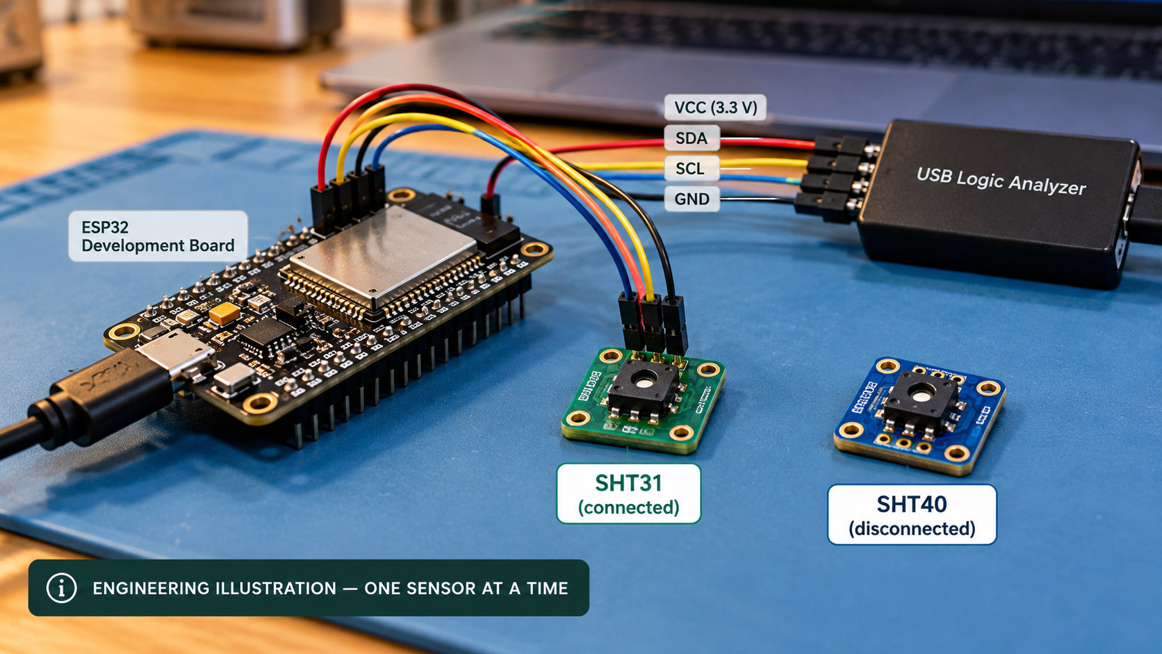
Confirm the actual sensor order code before setting kModel and kAddress; the sketch cannot identify a model from its address. This example uses GPIO21 for SDA and GPIO22 for SCL on a common ESP32 development board. Change those pins for your board, use a compatible 3.3 V bus, and test one device at a time if both use the same address. Open Serial Monitor at 115200 baud.
Run the comparison in four steps
- Check the unpowered wiring. Use common ground and a compatible 3.3 V sensor bus. Check the module schematic; do not connect two devices with the same address for this comparison.
- Configure the sketch. Use the Arduino IDE with the Arduino-ESP32 board package and select your actual ESP32 board and port. This sketch uses the built-in
WireAPI and needs no additional sensor library. SetkModeltoModel::SHT31orModel::SHT40. CheckkAddress, and the pins inWire.begin(21, 22, 100000)to match your hardware. - Upload and read the result. Open Serial Monitor at
115200baud. Resolve a bus or CRC error before comparing temperatures or humidity. - Change devices with power off. Update the model and address, upload again and retain both logs. These sequential logs check communication; they are not a matched accuracy test.
#include <Arduino.h>
#include <Wire.h>

enum class Model : uint8_t { SHT31, SHT40 };
enum class Result : uint8_t {
  ok, no_ack, write_failed, short_read,
  temp_crc_failed, rh_crc_failed
};

constexpr Model kModel = Model::SHT31;  // Set to Model::SHT40 for SHT40
constexpr uint8_t kAddress = 0x44;      // Check the exact order code or wiring

const char* resultName(Result r) {
  switch (r) {
    case Result::ok:              return "ok";
    case Result::no_ack:          return "no_ack";
    case Result::write_failed:    return "write_failed";
    case Result::short_read:      return "short_read";
    case Result::temp_crc_failed: return "temp_crc_failed";
    case Result::rh_crc_failed:   return "rh_crc_failed";
  }
  return "unknown";
}

uint8_t crc8(const uint8_t* data) {
  uint8_t crc = 0xFF;
  for (uint8_t i = 0; i < 2; ++i) {
    crc ^= data[i];
    for (uint8_t bit = 0; bit < 8; ++bit) {
      crc = (crc & 0x80)
          ? uint8_t((crc << 1) ^ 0x31)
          : uint8_t(crc << 1);
    }
  }
  return crc;
}

Result readSensor(float& temperatureC, float& humidityRH) {
  Wire.beginTransmission(kAddress);
  if (Wire.endTransmission() != 0) return Result::no_ack;

  Wire.beginTransmission(kAddress);
  if (kModel == Model::SHT31) {
    Wire.write(uint8_t(0x24));
    Wire.write(uint8_t(0x00));
  } else {
    Wire.write(uint8_t(0xFD));
  }
  if (Wire.endTransmission() != 0) return Result::write_failed;

  delay(kModel == Model::SHT31 ? 20 : 10);

  uint8_t count = Wire.requestFrom(kAddress, uint8_t(6));
  if (count != 6) {
    while (Wire.available()) Wire.read();
    return Result::short_read;
  }

  uint8_t data[6];
  for (uint8_t i = 0; i < 6; ++i) data[i] = Wire.read();

  if (crc8(&data[0]) != data[2]) return Result::temp_crc_failed;
  if (crc8(&data[3]) != data[5]) return Result::rh_crc_failed;

  uint16_t rawT = (uint16_t(data[0]) << 8) | data[1];
  uint16_t rawRH = (uint16_t(data[3]) << 8) | data[4];

  temperatureC = -45.0f + 175.0f * rawT / 65535.0f;
  humidityRH = (kModel == Model::SHT31)
      ? 100.0f * rawRH / 65535.0f
      : -6.0f + 125.0f * rawRH / 65535.0f;

  return Result::ok;
}

void setup() {
  Serial.begin(115200);
  Wire.begin(21, 22, 100000);
  Serial.println("model,address,status,temperature_c,humidity_rh");
}

void loop() {
  float temperatureC = 0.0f;
  float humidityRH = 0.0f;
  Result result = readSensor(temperatureC, humidityRH);

  Serial.print(kModel == Model::SHT31 ? "SHT31" : "SHT40");
  Serial.print(",0x");
  Serial.print(kAddress, HEX);
  Serial.print(",");
  Serial.print(resultName(result));
  if (result == Result::ok) {
    Serial.print(",");
    Serial.print(temperatureC, 2);
    Serial.print(",");
    Serial.print(humidityRH, 2);
  } else {
    Serial.print(",,");
  }
  Serial.println();
  delay(1000);
}
Read the output before comparing the sensors
The first line is model,address,status,temperature_c,humidity_rh. The formats below show the fields to expect; angle brackets stand for values from your own device.
SHT31,0x44,ok,<temperature_c>,<humidity_rh>
SHT40,0x44,ok,<temperature_c>,<humidity_rh>
SHT40,0x44,no_ack,,
SHT40,0x44,rh_crc_failed,,
Error rows keep the temperature and humidity fields empty, so every row has five CSV columns. The printed model is the value you selected in kModel, not a detected identity. An ok row means both CRC checks passed; still verify the model and RH equation. Follow the status table for a failed read. To judge accuracy, compare stable readings with an independent reference under matched conditions.
The 20 ms SHT31 and 10 ms SHT40 delays cover the high-repeatability single-shot commands used here. The sketch keeps the SHT40 RH calculation unclipped for diagnosis; after verifying the model and equation, a user-facing display can bound RH to 0–100%RH as described in the SHT4x datasheet. It does not implement SHT31 periodic mode, ALERT or nRESET, or either device’s heater functions. SHT3x-DIS datasheet; SHT4x quick start. For initial SHT40 wiring and first-read checks, see the SHT40 with ESP32 guide.
Can the existing SHT31 PCB take an SHT40?
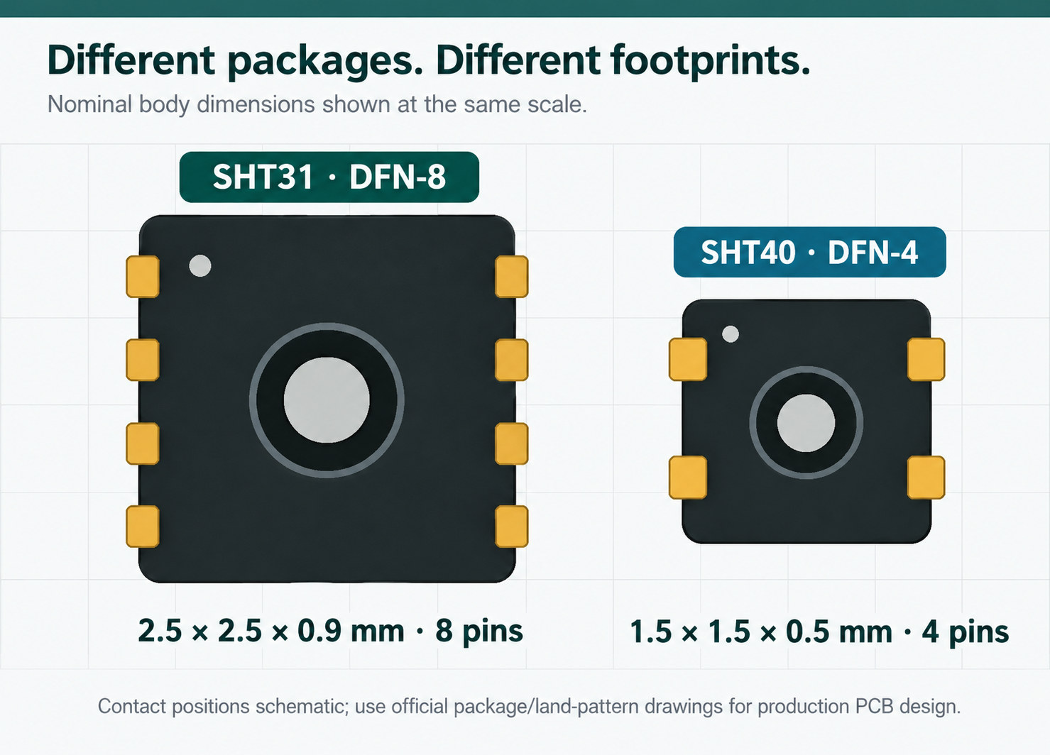
Not if the board directly mounts the standard bare SHT31 package. The SHT31 has an eight-contact, 2.5 × 2.5 × 0.9 mm package; the standard SHT40 has four contacts in a 1.5 × 1.5 × 0.5 mm package. Compare the exact mechanical drawings, pads, height, solder process and airflow location before redesigning the board. The contact positions in the diagram below are explanatory; production lands must follow the released drawings. .
Which nets change in the application circuit?
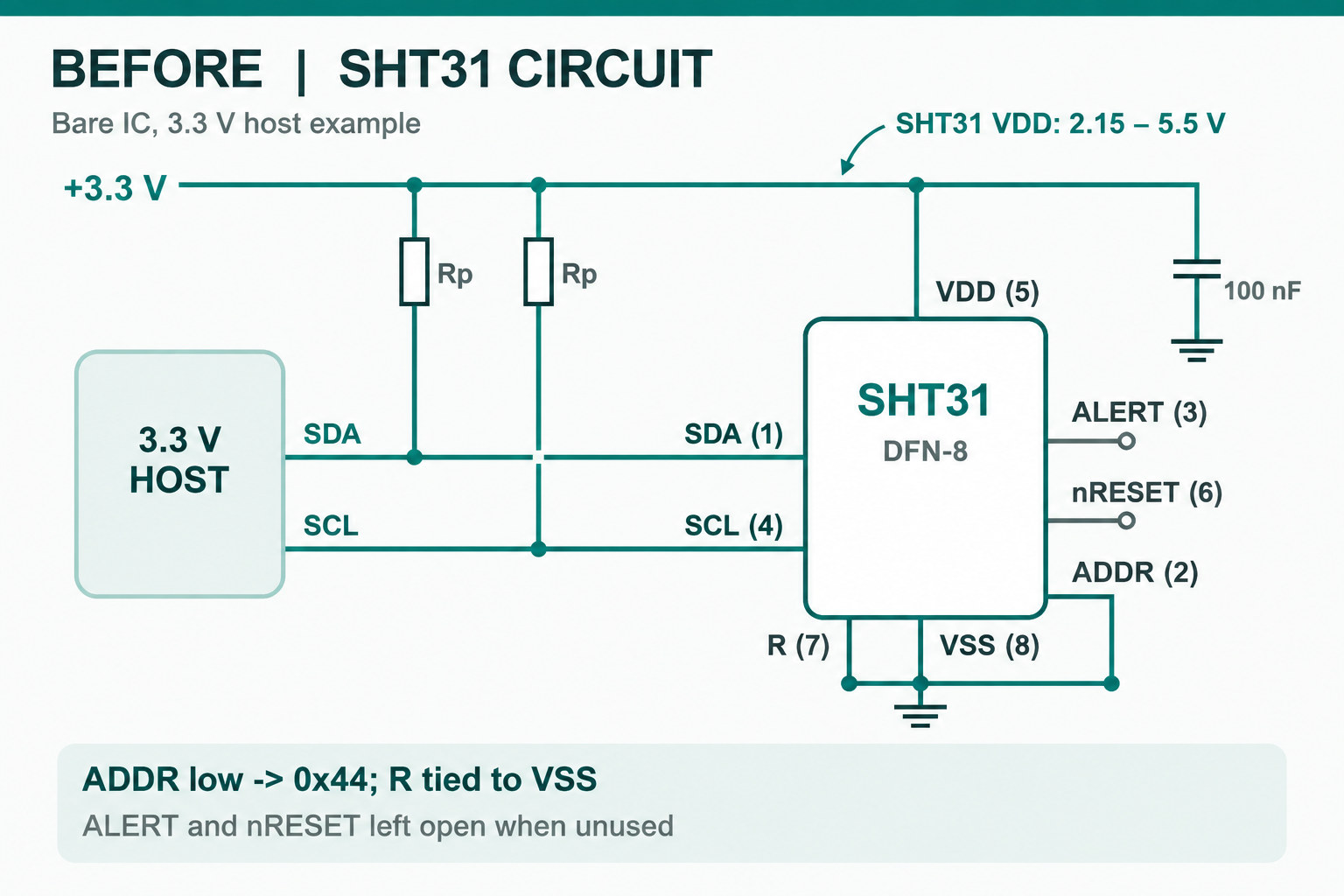
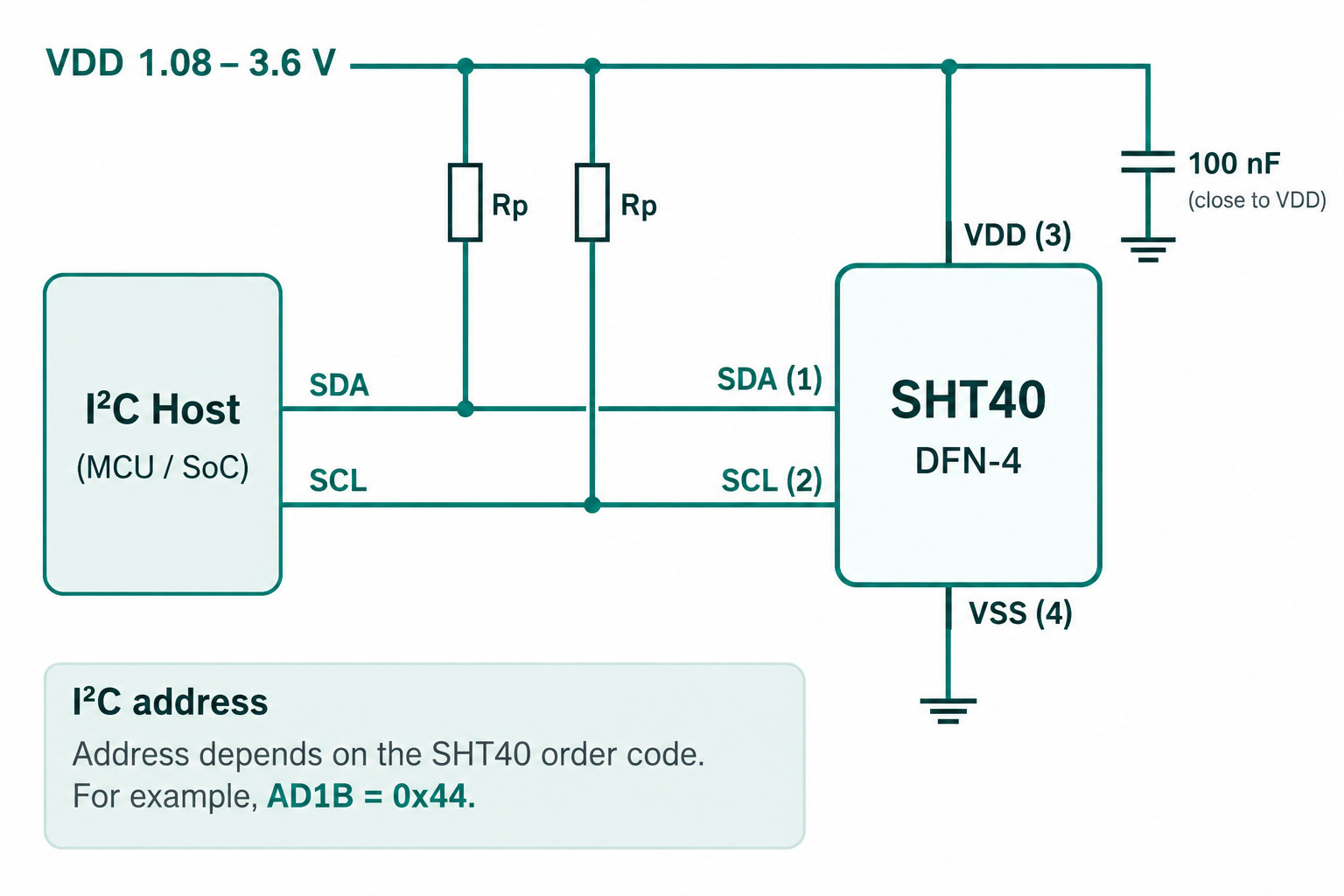
The next two schematics compare bare sensors on the same 3.3 V host bus. Both need SDA and SCL pull-ups to a compatible rail and local supply decoupling. Identical signal names do not make the packages or the extra SHT31 control pins interchangeable.
SHT31 vs SHT40 pinout: what changes on the PCB?
This is a signal mapping for the standard bare packages, not a pad-to-pad adapter layout. Locate pin 1 from the released package drawing before routing.
| Net | SHT31 pin | SHT40 pin | Required action |
|---|---|---|---|
| SDA | 1 | 1 | Reroute to the new pad; check the pull-up rail. |
| SCL | 4 | 2 | Reroute the clock and check bus timing. |
| VDD | 5 | 3 | Use a compatible supply and local decoupling. |
| VSS | 8 | 4 | Connect to common ground. |
| ADDR | 2 | None | Choose the SHT40 order code for the required address. |
| ALERT / nRESET | 3 / 6 | None | Redesign the dependent functions; these nets have no direct SHT40 equivalent. |
| R | 7, tied to VSS | None | There is no corresponding signal pad. |
Sources: SHT3x-DIS pin assignment, page 8 and SHT4x pin assignment, page 17. Review the center-pad assembly guidance separately; it is not another interchangeable signal pin.
Review three areas on the old schematic. Supply: an SHT31 design may use 5 V, but the standard SHT40 operating VDD range is 1.08–3.6 V. Bus pull-ups: changing sensor VDD alone does not fix SDA/SCL lines still pulled to 5 V; check every device on the bus. Extra functions: if the product uses SHT31 ALERT or nRESET, the four-pin SHT40 has no matching hardware pins. Select pull-up resistance from the bus electrical limits rather than copying a value from this illustration.
An external four-wire module is a different case. VCC, GND, SDA and SCL labels are only a starting point: check the board’s actual pin order, whether VIN includes a regulator, and the rail used by its I²C pull-ups. A bare-chip VDD rating does not describe every breakout’s VIN rating.
If the product calls SHT31 periodic mode, ALERT or nRESET, a successful SHT40 single-shot read cannot prove feature migration. Trace the deployed firmware and schematic separately; the result may be a firmware change, a PCB change, or a decision to keep the original platform.
Should you use SHT31 or SHT40?
There is no universal “better” choice. The correct part depends on whether the project is preserving an existing product or starting a new design. Do not use family generation alone as a replacement criterion.
| Design situation | Practical decision | Why |
|---|---|---|
| Existing SHT31 product that uses the current footprint, 5 V supply path, ALERT or nRESET | Keep the SHT31 architecture unless a controlled redesign is justified. | SHT40 is not a drop-in firmware, feature or bare-footprint replacement. |
| New compact 3.3 V design that does not depend on SHT31-specific control pins | SHT40 can be evaluated as a new-design candidate. | The smaller four-contact package can reduce board area, but the firmware and PCB still require model-specific implementation and validation. |
| Prototype using external four-wire breakout boards | Reuse the cable only after checking the module schematic and pin order. | VIN regulation and SDA/SCL pull-up rails can differ even when both boards expose VCC, GND, SDA and SCL. |
| Requirement is “no PCB change and no firmware change” | Do not treat SHT40 as a direct replacement. | Matching 0x44 does not remove the command, RH formula, package and feature differences. |
What evidence is enough to approve an SHT31-to-SHT40 migration?
Keep “communicates correctly” separate from “works in the finished product.” The first requires the verified address and command, complete six-byte response, both CRC values and the correct formula. The second requires a product-level check of airflow, PCB heat, enclosure openings, response and the project’s temperature/RH error limits. Compare the installed assemblies in matched conditions with an independent reference and record any placement effect. A single Serial Monitor screenshot cannot establish product acceptance.
Need a controlled migration review?
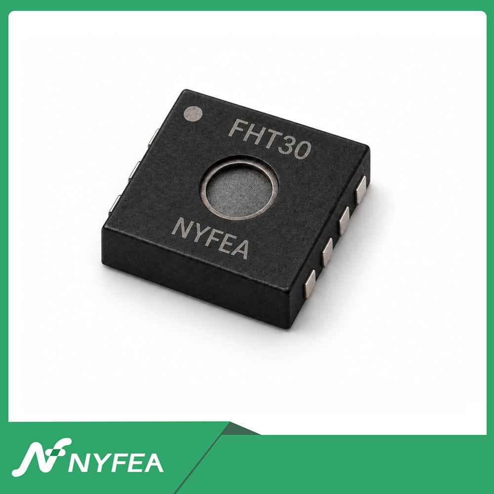
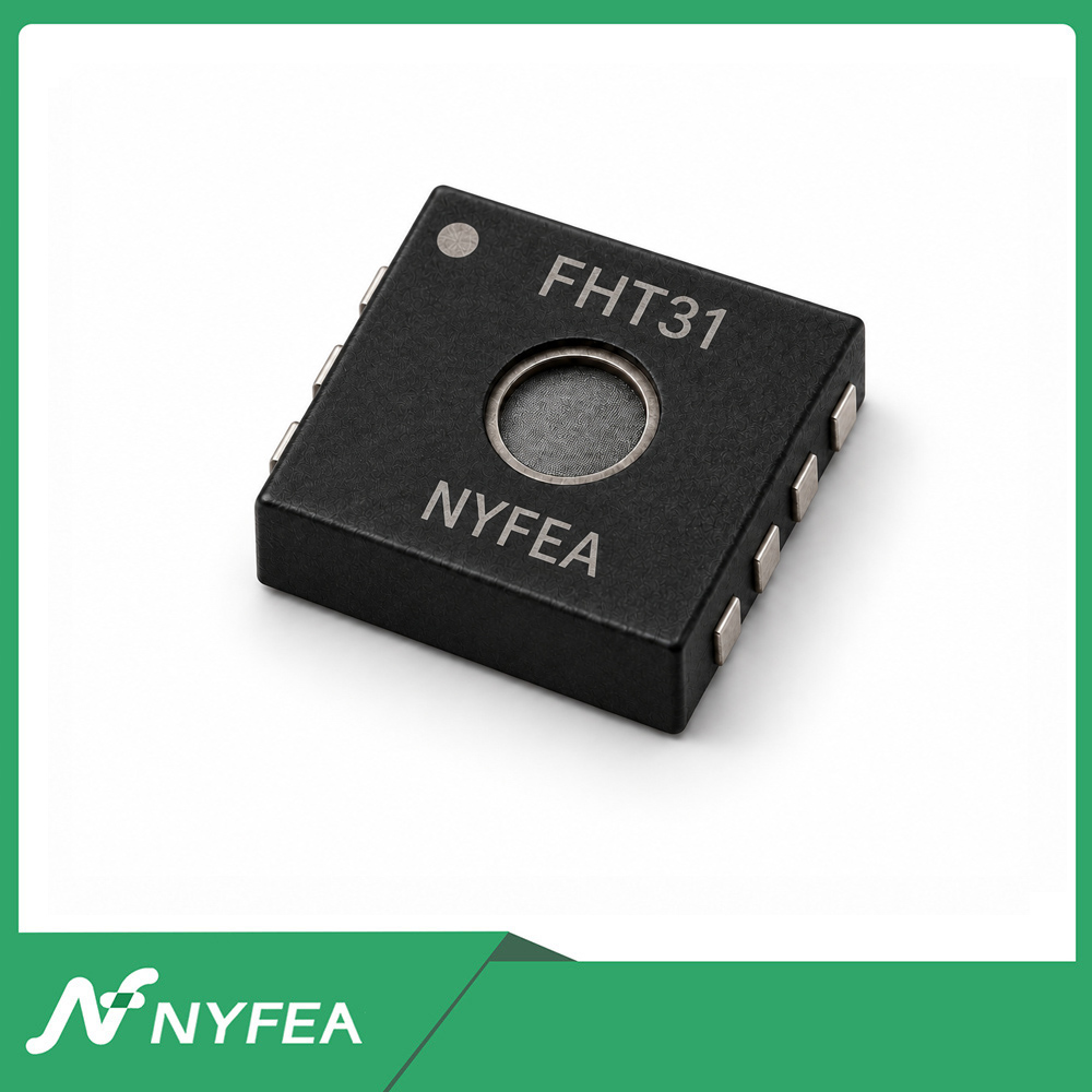
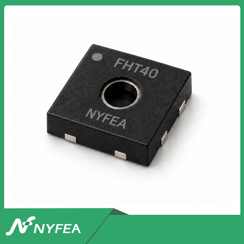
Qualify the exact order code, schematic, firmware path and finished assembly before approving a substitute. If you are separately evaluating NYFEA devices, review FHT31 for an eight-pin architecture or FHT40 for a four-pin redesign; neither is presented here as an automatic drop-in replacement.
Decision boundary: Keep the reusable I²C transfer, parser and CRC logic where verified; revise model-specific commands, RH conversion and feature calls; redesign the bare-chip footprint when moving from standard SHT31 to standard SHT40. Release a product change only against evidence from the actual assembly.
Common SHT31 vs SHT40 questions
Why is the humidity wrong even when both CRC checks pass?
CRC validates the received bytes, not the equation used afterward. Confirm the sensor order code and the model selected in the program. SHT31 and SHT40 use different RH conversion equations. If both are correct, investigate placement, heating and airflow before applying an offset.
Are SHT31 and SHT40 pin-compatible?
No. The standard bare SHT31 package has eight contacts in a 2.5 × 2.5 mm body, while the standard SHT40 package has four contacts in a 1.5 × 1.5 mm body. Use the released mechanical and land-pattern drawings for production PCB work.
Do SHT31 and SHT40 use the same I²C address?
They can. SHT31 commonly uses 0x44 and can select 0x45 with ADDR; SHT40 address behavior depends on the exact order code, with 0x44 common for the path discussed here. A matching address does not identify the sensor model.
Can the same Arduino or ESP32 driver be used for both?
Do not reuse an unchecked full driver. The six-byte parser and CRC-8 routine can be shared for the single-shot path shown here, but the trigger command and relative-humidity conversion are model-specific, and feature APIs such as periodic mode, ALERT, reset and heater behavior require separate review.
Can I reuse the same four-wire breakout wiring?
Only conditionally. Verify the board’s actual pin order, VIN circuitry, sensor supply and the voltage used by SDA/SCL pull-ups. Identical VCC, GND, SDA and SCL labels do not guarantee identical electrical behavior.
Can an SHT40 be used on an old 5 V SHT31 design?
Not by assumption. The standard SHT40 VDD range discussed here is 1.08–3.6 V, and the I²C pull-ups must also be checked. A 5 V rail elsewhere on the old board can still make the migration incompatible even if the sensor itself is powered from 3.3 V.
Why does 0x44 respond but the old SHT31 code still fail?
An I²C ACK only proves that a device responded at that address. SHT31 and SHT40 use different high-repeatability single-shot commands, and they use different RH conversion equations, so a transaction can fail—or worse, produce a plausible but wrong humidity value—when the model is not verified.
Which is better, SHT31 or SHT40?
It depends on the design. An existing product may favor the already-qualified SHT31 architecture, while a new compact 3.3 V product can evaluate SHT40 as a smaller-package option. The correct choice is based on electrical, mechanical, firmware and system-level requirements rather than generation alone.
Primary technical sources
- Sensirion SHTxx and STSxx Design Guide — PCB and enclosure thermal effects.
SHT31 and SHT40 are Sensirion product names. NYFEA is independent of Sensirion; the NYFEA devices linked above are candidates for separate qualification, not approved replacements by this article.