SHT40 with ESP32: Wiring, Complete I2C Code and Valid Readings
Direct answer. Seeing 0x44 in an I2C scan is a useful start, but it is not yet a temperature or humidity reading. Connect the specified SHT40 breakout to a 3.3 V ESP32 bus, send the single-shot command 0xFD, wait for conversion, and read all six response bytes. Check the CRC for both measurements before converting them to °C and %RH. The complete sketch below performs each step and prints a status that tells you where a failure occurred. To judge accuracy in a finished device, compare the assembled sensor with an independent reference.
What is the SHT40?
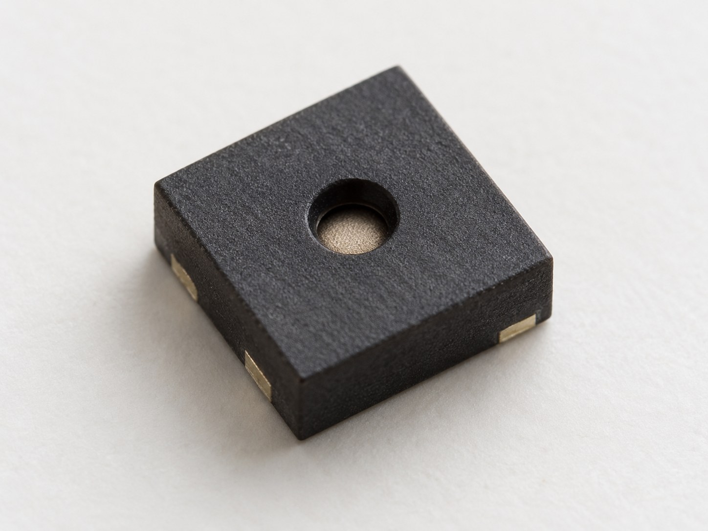
The SHT40 is a compact digital temperature and relative-humidity sensor in Sensirion’s SHT4x family. The bare sensor is a four-contact DFN package with a sensing opening centered on its top face. This guide uses the SHT40 on a breakout board, which brings its power and I²C connections to accessible pins for the ESP32 test.
Check the official SHT4x datasheet for the bare sensor’s package and electrical limits; check the breakout specifications for its board-level voltage rating.
1. Know which boards this guide uses
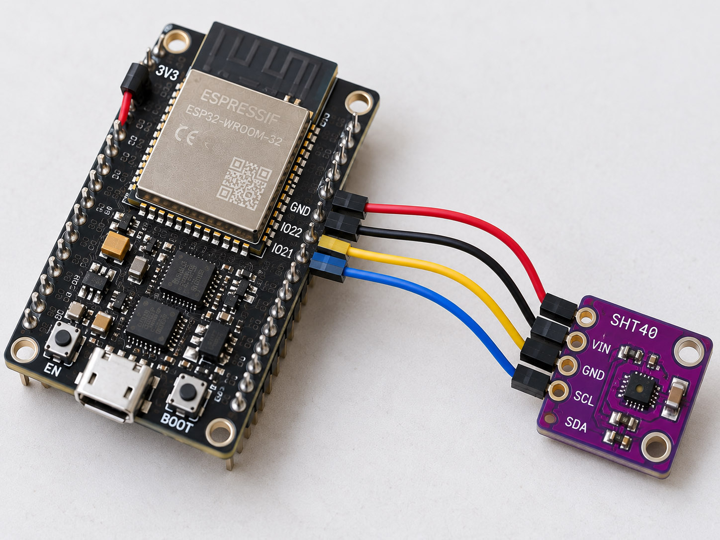
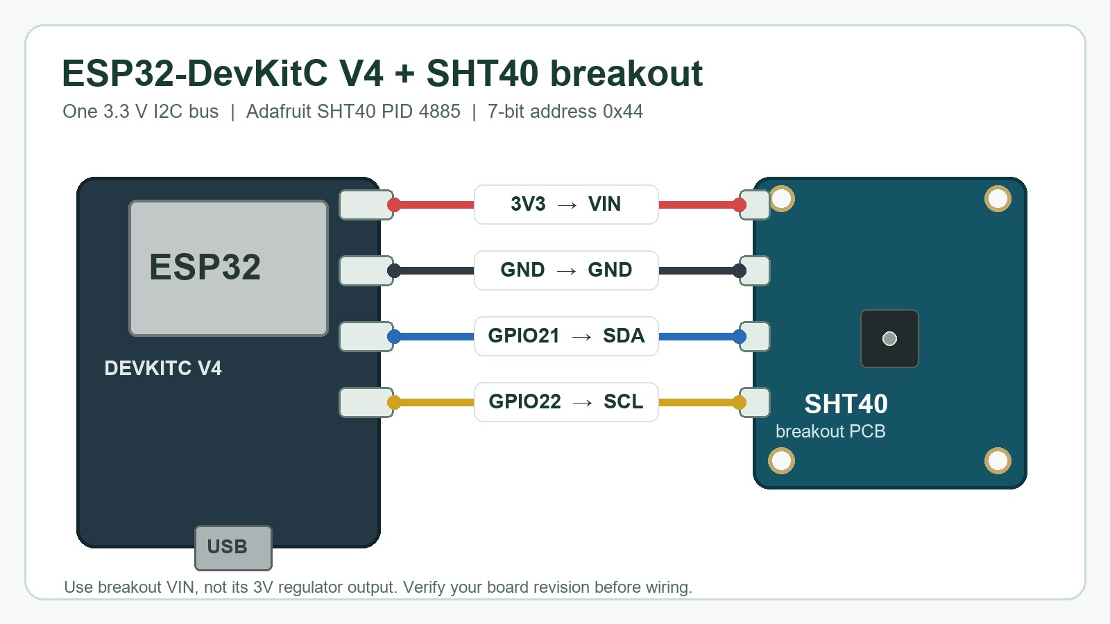
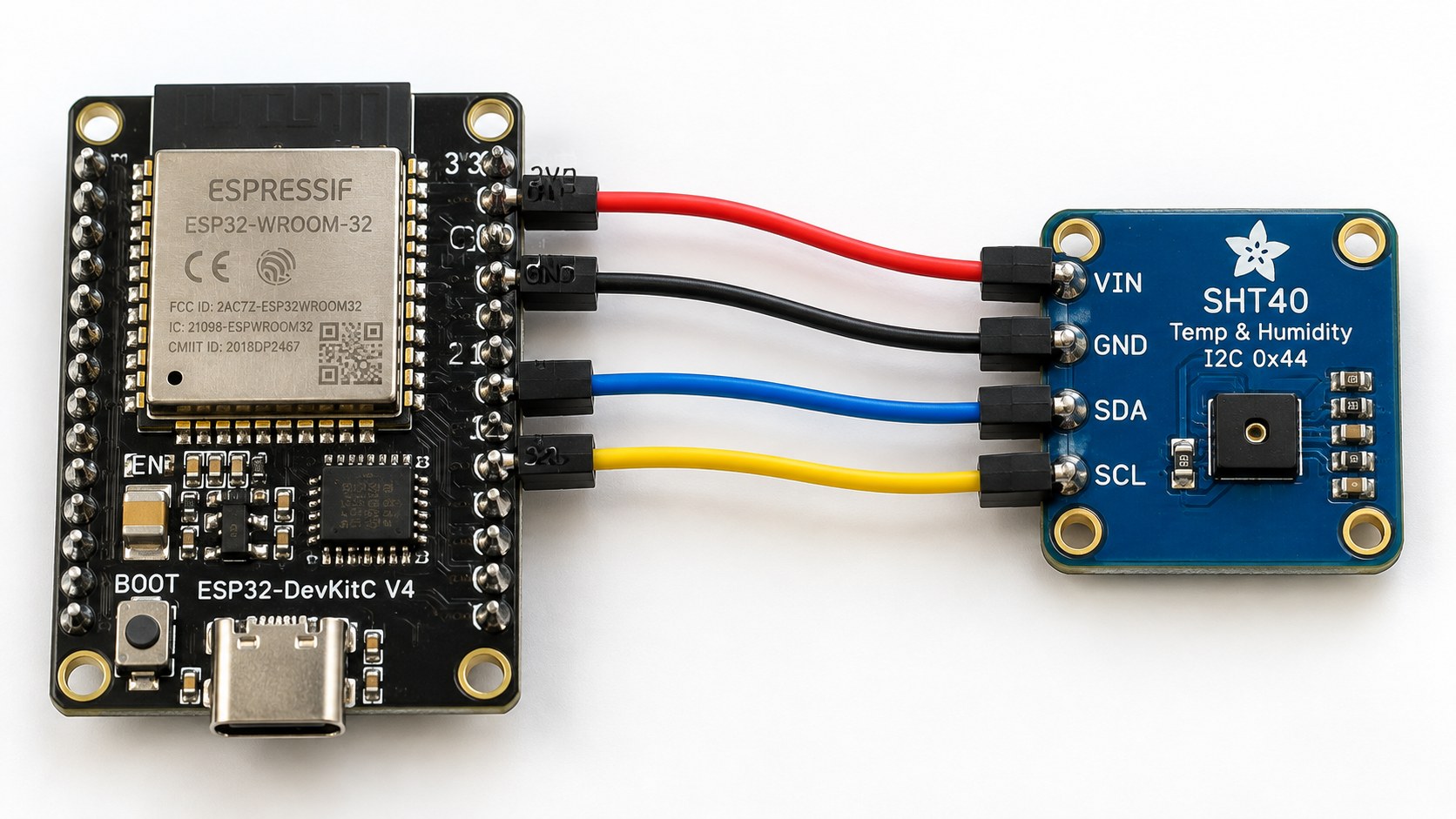
The wiring and code below are written for an ESP32-DevKitC V4 with ESP32-WROOM-32E, an Adafruit SHT40 breakout (PID 4885), and the Arduino-ESP32 Wire library. USB powers the ESP32; its 3V3 pin powers the breakout. This particular breakout uses 7-bit I2C address 0x44. Check the labels on your own boards before copying the wiring: other ESP32 variants and SHT40 carriers can differ.
Voltage is the first distinction to get right. The bare SHT4x sensor is specified for 1.08–3.6 V. Adafruit's PID 4885 breakout accepts 3.3–5 V at VIN because it has a regulator and I2C level shifting. The breakout's 5 V capability does not apply to an unprotected sensor IC.
2. Connect four wires and check the supply
| ESP32-DevKitC V4 | Adafruit SHT40 PID 4885 | Connection |
|---|---|---|
| 3V3 | VIN | Supply the breakout at 3.3 V |
| GND | GND | Share ground |
| GPIO21 | SDA | I2C data |
| GPIO22 | SCL | I2C clock |
Disconnect USB power before moving jumpers. Connect the breakout's VIN, not its 3V regulator-output pad. Its SDA and SCL already have pull-ups; if several modules share the bus, check their combined pull-up resistance. The sketch uses Wire.begin(21, 22), so changing ESP32 pins also means changing those two numbers in code. If the sensor disappears when connected, measure the supply at the breakout terminals before changing software.
3. Scan for 0x44, then verify a measurement
The sketch scans the I2C bus once at startup. An ack_only row means a device acknowledged 0x44 at that moment; it does not identify the device or verify temperature or humidity. The loop then sends 0xFD, waits 10 ms, reads six bytes, and checks the temperature and humidity CRCs separately. It prints crc_ok only after both CRCs and the temperature-range check pass.
If startup prints no_ack, the loop still retries 0x44 at about two-second intervals. While that address remains unreachable, expect command_nack rows. Disconnect USB power before checking VIN, common ground, GPIO21-to-SDA and GPIO22-to-SCL continuity. If the scan reports another address, identify that device and verify the exact SHT40 order code before changing SHT40_ADDR; the Adafruit PID 4885 used here is fixed at 0x44. Reset after rewiring to run the startup scan again.
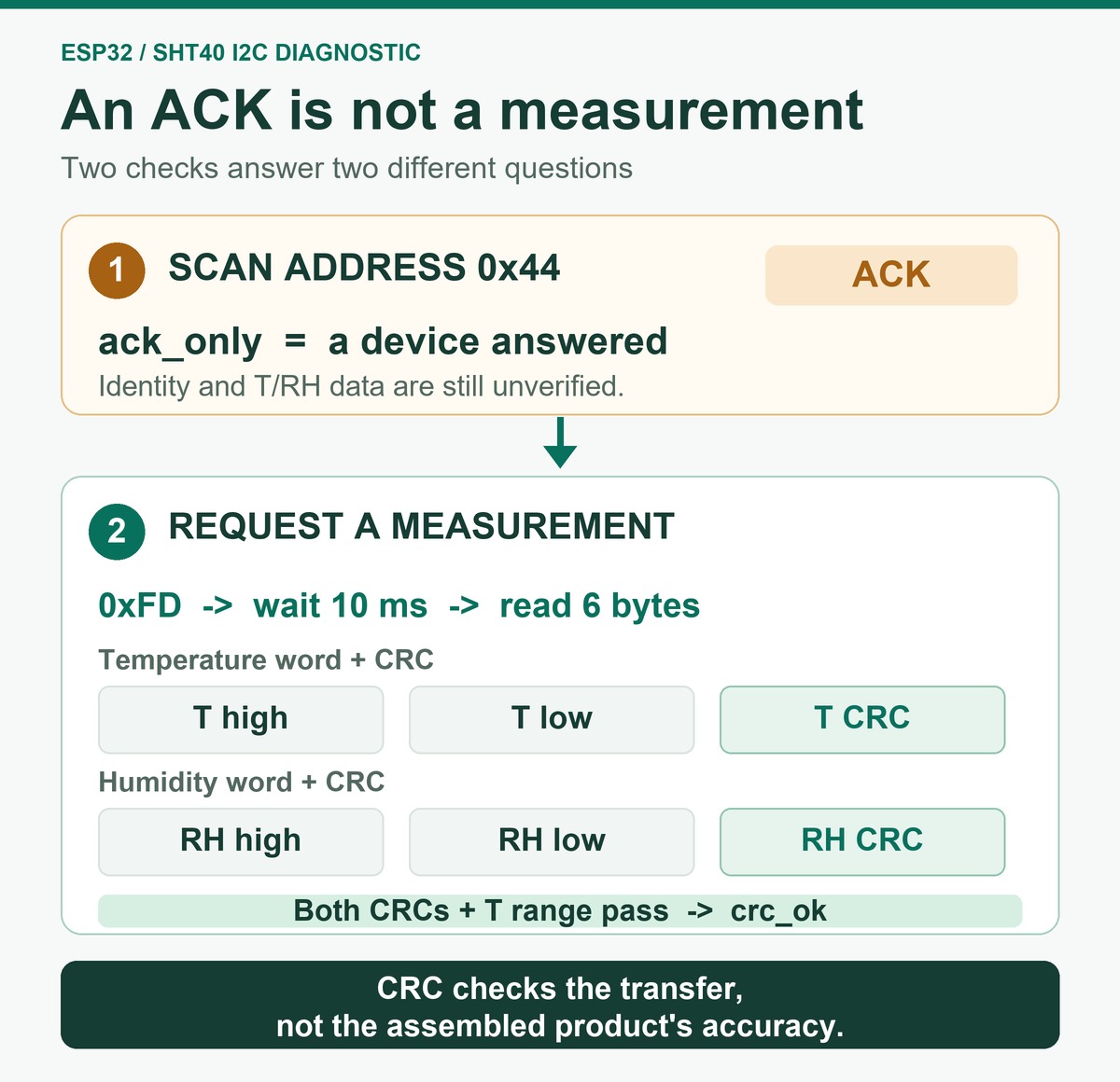
crc_ok; accuracy of the assembled product still needs a reference check.4. Upload one complete sketch
In Arduino IDE, select ESP32 Dev Module for this DevKitC-class board and choose its serial port. Copy the entire sketch below, upload it, then open Serial Monitor at 115200 baud. The sketch needs only Arduino.h and Wire.h; it does not depend on a separate SHT40 library.
#include <Arduino.h>
#include <Wire.h>

// ESP32-DevKitC V4 (ESP32-WROOM-32E) + Adafruit SHT40 breakout PID 4885.
// Both boards use 3.3 V logic in this example; use the breakout VIN pin.
constexpr int SDA_PIN = 21;
constexpr int SCL_PIN = 22;
constexpr uint8_t SHT40_ADDR = 0x44;
constexpr uint32_t SAMPLE_INTERVAL_MS = 2000;

uint8_t crc8(const uint8_t* data, size_t length) {
  uint8_t crc = 0xFF;
  for (size_t i = 0; i < length; ++i) {
    crc ^= data[i];
    for (uint8_t bit = 0; bit < 8; ++bit) {
      crc = (crc & 0x80) ? (uint8_t)((crc << 1) ^ 0x31)
                         : (uint8_t)(crc << 1);
    }
  }
  return crc;
}

void printPrefix(uint8_t level) {
  Serial.print(millis());
  Serial.print(',');
  Serial.print(level);
  Serial.print(F(",0x44,"));
}

void printStatus(uint8_t level, const __FlashStringHelper* status) {
  printPrefix(level);
  Serial.print(F(",,"));
  Serial.println(status);
}

void scanBus() {
  bool foundTarget = false;
  for (uint8_t address = 1; address < 127; ++address) {
    Wire.beginTransmission(address);
    if (Wire.endTransmission() == 0) {
      if (address == SHT40_ADDR) {
        foundTarget = true;
        printStatus(1, F("ack_only"));
      } else {
        Serial.print(F("# Other I2C device at 0x"));
        if (address < 16) Serial.print('0');
        Serial.println(address, HEX);
      }
    }
  }
  if (!foundTarget) printStatus(0, F("no_ack"));
}

void takeSample() {
  Wire.beginTransmission(SHT40_ADDR);
  Wire.write((uint8_t)0xFD);  // High-repeatability, single-shot measurement.
  if (Wire.endTransmission() != 0) {
    printStatus(0, F("command_nack"));
    return;
  }

  delay(10);  // SHT4x datasheet: 8.3 ms maximum for high repeatability.
  const uint8_t count = Wire.requestFrom(SHT40_ADDR, (uint8_t)6);
  if (count != 6) {
    while (Wire.available()) Wire.read();
    printStatus(1, F("short_read"));
    return;
  }

  uint8_t frame[6];
  for (uint8_t i = 0; i < 6; ++i) frame[i] = Wire.read();
  if (crc8(frame, 2) != frame[2] || crc8(frame + 3, 2) != frame[5]) {
    printStatus(2, F("crc_error"));
    return;
  }

  const uint16_t rawT = ((uint16_t)frame[0] << 8) | frame[1];
  const uint16_t rawRH = ((uint16_t)frame[3] << 8) | frame[4];
  const float temperatureC = -45.0f + 175.0f * rawT / 65535.0f;
  float humidityRH = -6.0f + 125.0f * rawRH / 65535.0f;
  if (humidityRH < 0.0f) humidityRH = 0.0f;
  if (humidityRH > 100.0f) humidityRH = 100.0f;

  if (temperatureC < -40.0f || temperatureC > 125.0f) {
    printStatus(2, F("outside_temperature_spec"));
    return;
  }

  printPrefix(3);
  Serial.print(temperatureC, 2);
  Serial.print(',');
  Serial.print(humidityRH, 2);
  Serial.println(F(",crc_ok"));
}

void setup() {
  Serial.begin(115200);
  delay(250);
  Wire.begin(SDA_PIN, SCL_PIN);
  Wire.setClock(100000);
  Serial.println(F("ms,level,address,temperature_c,humidity_rh,status"));
  scanBus();
}

void loop() {
  takeSample();
  delay(SAMPLE_INTERVAL_MS);
}
Each measurement returns temperature MSB, temperature LSB, temperature CRC, humidity MSB, humidity LSB, humidity CRC. The sketch sends 0xFD, waits 10 ms against the datasheet's 8.3 ms maximum high-repeatability conversion time, and checks the two CRC-8 bytes separately (polynomial 0x31, initial value 0xFF). It rejects a short or corrupted response instead of repeating an old number. Calculated RH is clipped to 0–100 %RH for display. If the log shows exactly 0 or 100 %RH, the raw value may have been clipped; crc_ok does not establish that ambient humidity was exactly at that boundary. Retain the raw humidity word when debugging boundary readings. The two-second pause between attempts is only a convenient bring-up interval.
5. Read the log: from address to usable data
The first line is ms,level,address,temperature_c,humidity_rh,status. The following shows the format, not measured test data:
ms,level,address,temperature_c,humidity_rh,status
<elapsed_ms>,1,0x44,,,ack_only
<elapsed_ms>,3,0x44,<temperature>,<humidity>,crc_ok
ms is elapsed ESP32 time, not a wall-clock timestamp. Keep these four questions separate:
- Did the address answer?
ack_onlyestablishes an I2C response, not sensor identity. - Did six bytes arrive?
short_readmeans the frame was incomplete. A complete frame can still be wrong. - Did both CRCs pass?
crc_okmarks a usable bring-up sample after conversion and a temperature-range check;crc_errormust be discarded. CRC checks transmission integrity, not calibration. - Does the assembled product measure correctly? Compare stable, time-aligned temperature and RH readings with a suitable independent reference under representative conditions. Firmware cannot award itself this level.
The numeric level is a quick progress marker: 0 means no usable response, 1 means an address answered or a read was incomplete, 2 means a complete frame failed integrity or range checks, and 3 means a CRC-checked measurement was printed. The status text gives the precise reason. The fourth question—accuracy of the finished product—cannot be answered by this sketch. Add a synchronized host timestamp if you need to compare longer logs with a reference instrument.
6. Troubleshoot the first failed step
| What you see | What it tells you | Check next |
|---|---|---|
no_ack at startup |
Nothing answered at 0x44 |
Breakout voltage, common ground, SDA/SCL continuity, actual part address and other bus devices. |
command_nack after an earlier ACK |
Communication changed or the sensor did not accept the command | Supply and bus stability, wiring, address and whether the device is still busy. |
short_read |
Fewer than six response bytes arrived | Conversion delay, wiring length, pull-ups and I2C signal quality. |
crc_error |
Six bytes arrived but failed integrity checking | Ground path, pull-ups, leads and how often the error recurs. Do not use that sample. |
crc_ok but implausible T or RH |
The transfer passed; the environment or device may still be wrong | Heat from the host, blocked airflow, moisture exposure, wrong device identity and a reference comparison. |
The SHT4x does not clock-stretch. A read attempted before conversion completes can receive a NACK. A successful read also consumes that measurement, so send a new command for the next sample. If failures are intermittent, retain failed rows in the log instead of graphing only the successful values.
7. When a plausible reading is still wrong
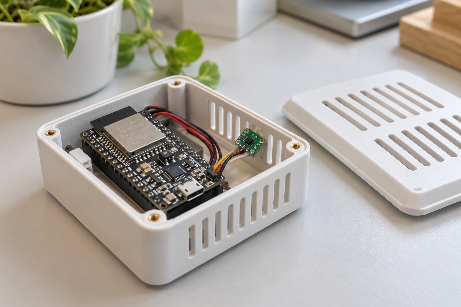
Suppose temperature rises and RH falls after you close the enclosure. That pattern can occur when the sensor sees air warmed by the ESP32 regulator, a charger or a display rather than the air you intend to measure. Relative humidity depends on temperature; a sound I2C transaction cannot correct a placement error.
Keep the sensing opening in representative airflow, away from warm copper, trapped pockets and handling. Allow the assembly to settle after power-up or an enclosure change, then record temperature and RH together. When comparing two locations, swap the sensor assemblies while keeping each electrical channel and code identity. If the difference follows the location, investigate airflow or heating. If it follows the device, investigate the assembly and sensor. One believable room reading is not an accuracy test.
8. From a bench reading to a product decision
Once crc_ok is repeatable, test the finished assembly over its intended supply range, I2C loading, enclosure airflow, temperature and humidity conditions. Compare time-aligned data with a suitable reference, define an error budget, and retain failure counts alongside good samples. Recheck after production steps or exposure that can affect the sensing opening. This evidence determines whether the design meets its own limits; an address scan and a room-temperature screenshot do not.
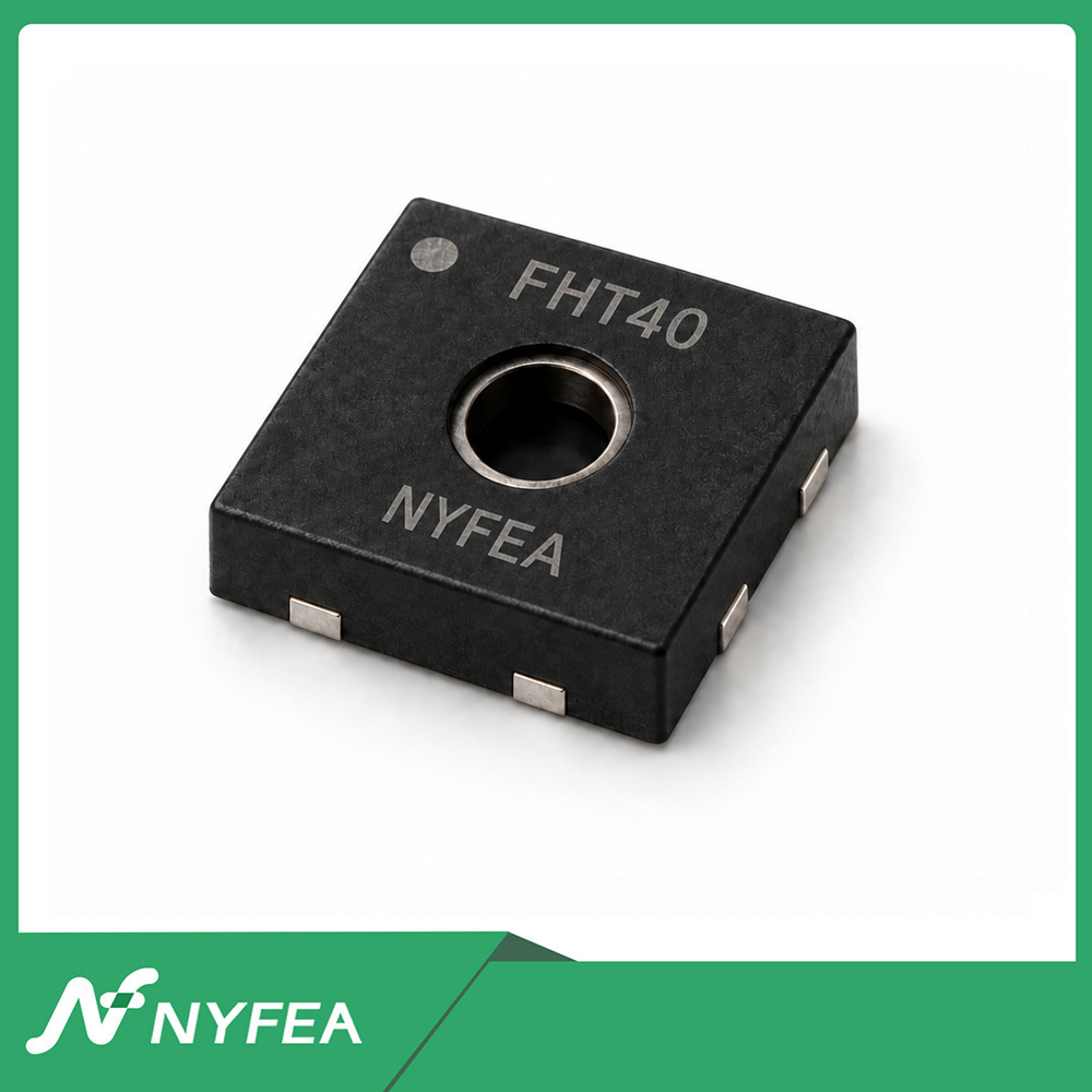
If the project needs another sensor source, NYFEA FHT40 can be evaluated at this stage. Compare its controlled specification with the original design's supply, footprint, pinout, commands, CRC, timing and accuracy conditions before changing hardware or firmware. Do not assume that the SHT40 sketch or breakout wiring also applies to a bare FHT40. A shared address alone is not a replacement decision. If condensation or heater recovery is part of the requirement, use the SHT40 heater and recovery guide as a separate test path.
9. Optional: pair SHT40 readings with GPS coordinates
An ESP32 can pair SHT40 temperature and relative-humidity readings with a GPS location for a moving environmental logger. The SHT40 stays on I2C; a UART GPS receiver, such as a NEO-6M-based module, uses a separate serial port. The four SHT40 connections above remain the same.
| Device | Device pin | ESP32 connection | What it does |
|---|---|---|---|
| Adafruit SHT40 breakout | VIN | 3V3 | Breakout supply for this setup |
| Adafruit SHT40 breakout | GND | GND | Common ground |
| Adafruit SHT40 breakout | SDA | GPIO21 | I2C data |
| Adafruit SHT40 breakout | SCL | GPIO22 | I2C clock |
| UART GPS receiver | VCC | Supply permitted by the exact GPS board | Check the carrier board's input-voltage rating |
| UART GPS receiver | GND | GND | Common ground |
| UART GPS receiver | TX | GPIO16 (ESP32 RX2) | Position messages from GPS to ESP32 |
| UART GPS receiver | RX | GPIO17 (ESP32 TX2), optional | Commands from ESP32 to GPS, if needed |
Check the GPS carrier's supply and UART logic levels before connecting it. A bare u-blox NEO-6M has a 2.7–3.6 V supply range; a carrier board may have its own regulator and a different input rating, so the label “NEO-6M” alone is not permission to apply 5 V. Espressif lists GPIO16 and GPIO17 as available on ESP32-DevKitC boards with WROOM or SOLO modules; they are reserved on WROVER versions. Confirm the exact ESP32 module before using those pins.
A GPS data stream is not yet a geotagged measurement. The sketch above reports SHT40 status only; it does not parse GPS messages or output coordinates. For a location-tagged record, read the GPS receiver on a separate UART at its configured baud rate, require a valid position fix, and associate its timestamp and coordinates with a SHT40 sample that passed both CRC checks. If no valid fix is available, retain the sensor sample with a no_fix location state rather than treating missing or stale coordinates as current.
Evaluate NYFEA FHT40 for the finished design
Check the current product data before starting a side-by-side evaluation.
Review the FHT40 specification10. Short FAQ
Can I power the SHT40 from the ESP32 5 V pin?
Not as wired here. A bare SHT40 is rated for 1.08–3.6 V. Adafruit PID 4885 accepts 3.3–5 V at its breakout VIN, but this example uses the ESP32's 3V3 pin.
Does 0x44 in an I2C scan mean the sensor works?
No. It means an address answered. Send a measurement command, read six bytes and validate both CRCs.
Why is Serial Monitor unreadable?
Set it to 115200 baud to match Serial.begin(115200). If the header is readable but samples fail, investigate I2C rather than the serial setting.
Does crc_ok prove accurate RH?
No. It proves that the received measurement frame passed its integrity checks. Accuracy in your product needs a controlled comparison with an independent reference.
Can the UART GPS receiver share the SHT40's SDA and SCL pins?
Not in this wiring. The SHT40 uses I2C on GPIO21 and GPIO22; the UART GPS receiver sends data to ESP32 RX2 on GPIO16. GPS RX on GPIO17 is optional when the ESP32 must send commands.
Can I connect a NEO-6M GPS module to 5 V?
Only if the exact carrier board specifies a 5 V input. The bare u-blox NEO-6M supply is rated for 2.7–3.6 V. Check the carrier's regulator and UART logic levels before wiring.
Why do I see GPS serial data but no coordinates?
Receiving GPS messages does not prove a valid position fix. Check the receiver's fix indication and antenna conditions; mark the location no_fix until a valid fix is available. Do not substitute an old position for the current sensor sample.
Are GPIO16 and GPIO17 available on every ESP32-DevKitC V4?
No. Espressif lists them as available on WROOM and SOLO versions, but reserved for internal use on WROVER versions. Check the module on your board before assigning the GPS UART.
SHT40 and Sensirion are identifiers or trademarks of their respective owners. NYFEA FHT40 is an independent product; this article does not claim an affiliation or an approved replacement relationship.