
PTC0603-0805X471 Chip PTC Thermistors
The NYFEA PTC0603-0805X471 Series comprises passive, two-terminal chip positive-temperature-coefficient thermistors. The electrical tables specify 470 Ω ±50% at 25 °C, a 32 V allowable voltage, and package-specific Curie and sensing-temperature options. The accompanying typical R–T plots illustrate the steep transition region; they are not continuous production min/max limits.
Product scope: These parts are resistive switching elements, not linear temperature sensors, digital temperature ICs, resettable fuses, relays, or complete overtemperature-protection systems. The external circuit must supply bias, detect the resistance transition, apply hysteresis or filtering where needed, and execute the final safe response.
Use the controlled product specification and the exact listed part number for purchasing, PCB release, test limits and production qualification.
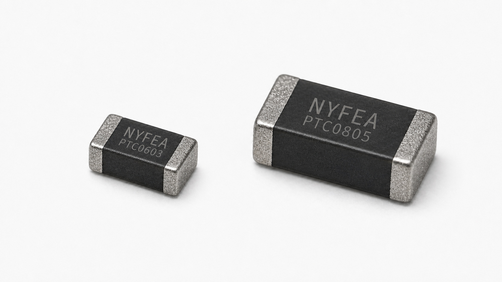
PTC0603-0805X471 Product Overview and Scope
The series supports temperature-threshold detection in compact electronics. Selection begins with package size and Curie-temperature code, then proceeds to sensing threshold, working-temperature range, bias circuit, thermal placement and fault response.
| Selection question | Specification answer | System-level decision |
|---|---|---|
| What is the sensing element? | Passive chip PTC thermistor; R25 = 470 Ω ±50%. | Provide external bias, readout and protection action. |
| Which packages are listed? | 0603 / 1608 metric and 0805 / 2012 metric. | Use package-specific dimensions and land patterns. |
| What defines the Curie temperature? | The temperature at which resistance reaches twice R25. | Do not confuse it with the 4.7 kΩ or 47 kΩ sensing temperatures. |
| What is the allowable voltage? | 32 V for every listed electrical part number. | Verify worst-case bias, transient and fault voltage. |
| Is it a precision linear sensor? | No; the intended characteristic is a steep resistance transition. | Use threshold detection and validate hysteresis and thermal lag. |
Package and Part-Number Selection
- Two package options: 0603 (1608 metric) and 0805 (2012 metric).
- Nominal R25: 470 Ω with ±50% tolerance for the listed parts.
- Allowable voltage: 32 V.
- Curie-temperature codes: 0603 lists 60 °C through 120 °C; 0805 lists 60 °C through 110 °C.
- Listed sensing tolerance: Q-coded electrical part numbers use ±5 °C at the 4.7 kΩ sensing point.
- Packing: paper tape, 4,000 pieces per reel for both packages.
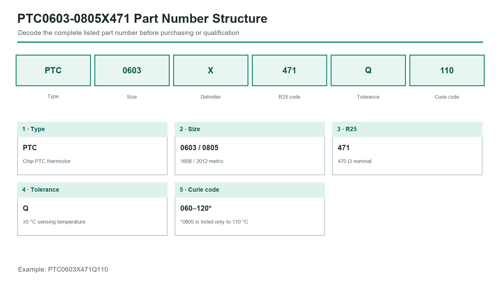
| Field | Meaning | Value in the listed series |
|---|---|---|
| PTC | Component category | Chip PTC thermistor |
| 0603 / 0805 | Package code | 1.60 × 0.80 × 0.80 mm / 2.00 × 1.25 × 0.85 mm |
| X | Delimiter | Fixed ordering delimiter |
| 471 | Nominal zero-power resistance code | 470 Ω at 25 °C |
| Q | Sensing-temperature tolerance code | ±5 °C in the listed electrical part numbers |
| 060 to 120 | Curie-temperature code | 60 °C to 120 °C, subject to the package-specific listed combinations |
PTC Switching Principle and Curie Temperature
Below the transition region, resistance changes relatively slowly. Above it, resistance rises steeply. This switching behavior can produce a clear electrical indication of temperature threshold crossing without implying linear temperature accuracy.
R25 = 470 Ω
Nominal resistance at 25 °C with ±50% tolerance.
R = 2 × R25
The specification defines Curie temperature as the temperature at which resistance equals twice R25, with R25 determined by the stated measurement method.
4.7 kΩ point
Q-coded parts list a package- and Curie-code-specific sensing temperature with ±5 °C tolerance.
47 kΩ point
Listed only for the PTC0603 table, with ±7 °C tolerance.
The PDF also provides typical R–T curves. Use them for qualitative understanding of the transition shape, not as production min/max resistance limits at every temperature. Base threshold selection on the tabulated values assigned to the exact part number, then validate supply, mounting, temperature ramp rate, hysteresis and lot variation in the finished assembly.
Threshold Circuit and Signal Interpretation
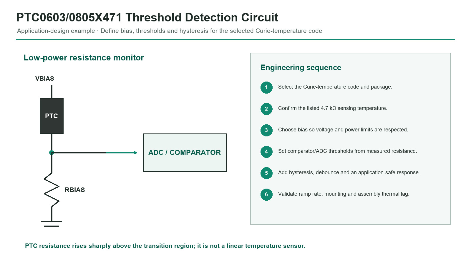
A divider, comparator or ADC can monitor the PTC resistance transition. The voltage across the thermistor must not exceed the listed 32 V allowable voltage under steady-state or fault conditions. Bias power must also be low enough that self-heating does not materially shift the intended switching point.
Bias Power, Trip Margin, and Hysteresis
The PTC is passive, so power is set by the external circuit. Calculate worst-case voltage and current using the broad R25 tolerance and the rising R–T characteristic, then validate whether self-heating changes the switching result.
| Design variable | Required check | Why it matters |
|---|---|---|
| Bias voltage | Worst-case steady-state and transient value remains ≤32 V | The allowable voltage is a component limit, not a target operating voltage. |
| Threshold | Map measured divider voltage to the selected 4.7 kΩ or other validated resistance point | Curie temperature and sensing temperature are not interchangeable. |
| Hysteresis | Define separate assert and release behavior | Prevents oscillation when temperature or resistance is near the trip point. |
| Thermal placement | Measure the offset to the protected object | The PTC senses its own body temperature. |
| Fault response | Define open, short and implausible-rate handling | The PTC alone does not execute a safe shutdown. |
Electrical Characteristics, Test Conditions, and Dimensions
Listed Electrical Part Numbers
| Listed part number | Curie temperature | Sensing temperature at 4.7 kΩ | Sensing temperature at 47 kΩ | Allowable voltage | R25 | Working-temperature range |
|---|---|---|---|---|---|---|
| PTC0603X471Q120 | 120 °C | 135 ±5 °C | 150 ±7 °C | 32 V | 470 Ω ±50% | −40 °C to +160 °C |
| PTC0603X471Q110 | 110 °C | 125 ±5 °C | 140 ±7 °C | 32 V | 470 Ω ±50% | −40 °C to +150 °C |
| PTC0603X471Q100 | 100 °C | 115 ±5 °C | 130 ±7 °C | 32 V | 470 Ω ±50% | −40 °C to +140 °C |
| PTC0603X471Q090 | 90 °C | 105 ±5 °C | 120 ±7 °C | 32 V | 470 Ω ±50% | −40 °C to +130 °C |
| PTC0603X471Q080 | 80 °C | 95 ±5 °C | 110 ±7 °C | 32 V | 470 Ω ±50% | −40 °C to +120 °C |
| PTC0603X471Q070 | 70 °C | 85 ±5 °C | 100 ±7 °C | 32 V | 470 Ω ±50% | −40 °C to +110 °C |
| PTC0603X471Q060 | 60 °C | 75 ±5 °C | 90 ±7 °C | 32 V | 470 Ω ±50% | −40 °C to +100 °C |
| PTC0805X471Q110 | 110 °C | 125 ±5 °C | Not listed | 32 V | 470 Ω ±50% | −40 °C to +140 °C |
| PTC0805X471Q100 | 100 °C | 115 ±5 °C | Not listed | 32 V | 470 Ω ±50% | −40 °C to +130 °C |
| PTC0805X471Q090 | 90 °C | 105 ±5 °C | Not listed | 32 V | 470 Ω ±50% | −40 °C to +120 °C |
| PTC0805X471Q080 | 80 °C | 95 ±5 °C | Not listed | 32 V | 470 Ω ±50% | −40 °C to +110 °C |
| PTC0805X471Q070 | 70 °C | 85 ±5 °C | Not listed | 32 V | 470 Ω ±50% | −40 °C to +100 °C |
| PTC0805X471Q060 | 60 °C | 75 ±5 °C | Not listed | 32 V | 470 Ω ±50% | −40 °C to +90 °C |
“Not listed” means the PTC0805 electrical table does not provide a 47 kΩ sensing-temperature column. It is not a zero value and must not be inferred from the 0603 table.
Test and Measurement Conditions
| Item | Specification method | Engineering interpretation |
|---|---|---|
| Standard atmosphere | 20 ±15 °C; 65 ±20% RH; 86–106 kPa | Applies unless another condition is specified. |
| Dispute reference | 25 ±2 °C; 65 ±5% RH; 86–106 kPa | Use these tighter conditions if results are disputed. |
| R25 | After maximum allowable voltage for 3 min and 2 h at 25 °C; measure below 1.5 V DC and below 10 mA | Follow the stated sequence; do not substitute an NTC zero-power test method. |
| Curie temperature | Temperature where resistance equals twice R25 | This is the specification definition; it is distinct from the listed 4.7 kΩ and 47 kΩ sensing temperatures. |
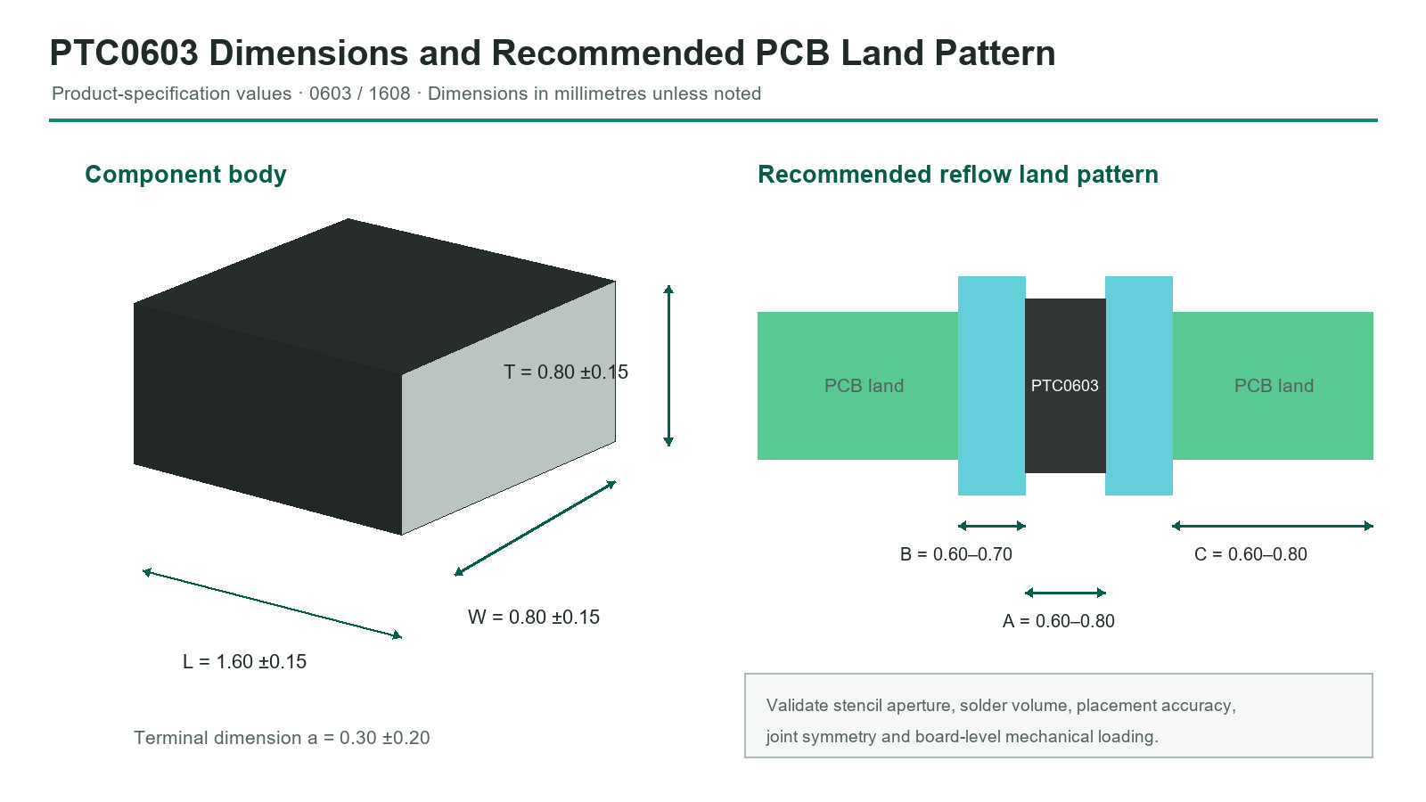
Mechanical Dimensions and Recommended PCB Lands
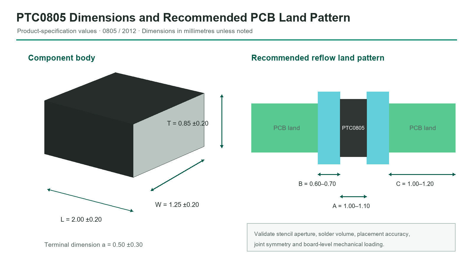
| Parameter | 0603 / 1608 metric | 0805 / 2012 metric |
|---|---|---|
| Body L | 1.60 ±0.15 mm | 2.00 ±0.20 mm |
| Body W | 0.80 ±0.15 mm | 1.25 ±0.20 mm |
| Body T | 0.80 ±0.15 mm | 0.85 ±0.20 mm |
| Terminal a | 0.30 ±0.20 mm | 0.50 ±0.30 mm |
| Land A | 0.60 to 0.80 mm | 1.00 to 1.10 mm |
| Land B | 0.60 to 0.70 mm | 0.60 to 0.70 mm |
| Land C | 0.60 to 0.80 mm | 1.00 to 1.20 mm |
PCB Assembly, Reliability, Packing, and Storage
Use the package-specific land pattern and qualify stencil, placement, reflow and board-flex conditions. The ceramic body is fragile and must not be used as a mechanical support.
| Test | Condition | Requirement |
|---|---|---|
| Terminal strength | 5 N for 10 ±1 s | No termination removal, ceramic split or other defect. |
| Board flexure | 2 mm; <0.5 mm/s; 10 ±1 s | No visible damage; |ΔR25/R25| ≤20%. |
| Vibration | 10–55 Hz; 1.5 mm total amplitude; 2 h per axis | No visible damage. |
| Drop | 1 m onto concrete, 10 times | No visible damage. |
| Solderability | 245 ±5 °C for 3 ±0.3 s | At least 95% wetting coverage. |
| Soldering heat | 260 ±5 °C for 10 ±1 s after 150 ±5 °C preheat for 90–120 s | No visible damage; |ΔR25/R25| ≤20%. |
| Temperature cycling | Five unloaded cycles between the selected part's minimum and maximum working temperatures | No visible damage; |ΔR25/R25| ≤20%. |
| Damp heat | 60 ±2 °C; 90 ±5% RH; 500 +24/−0 h | No visible damage; |ΔR25/R25| ≤20%. |
| High-temperature load | Maximum working temperature ±2 °C; maximum voltage; 1000 ±48 h | No visible damage; |ΔR25/R25| ≤20%. |
| Soldering method | Specified limits | Maximum cycles |
|---|---|---|
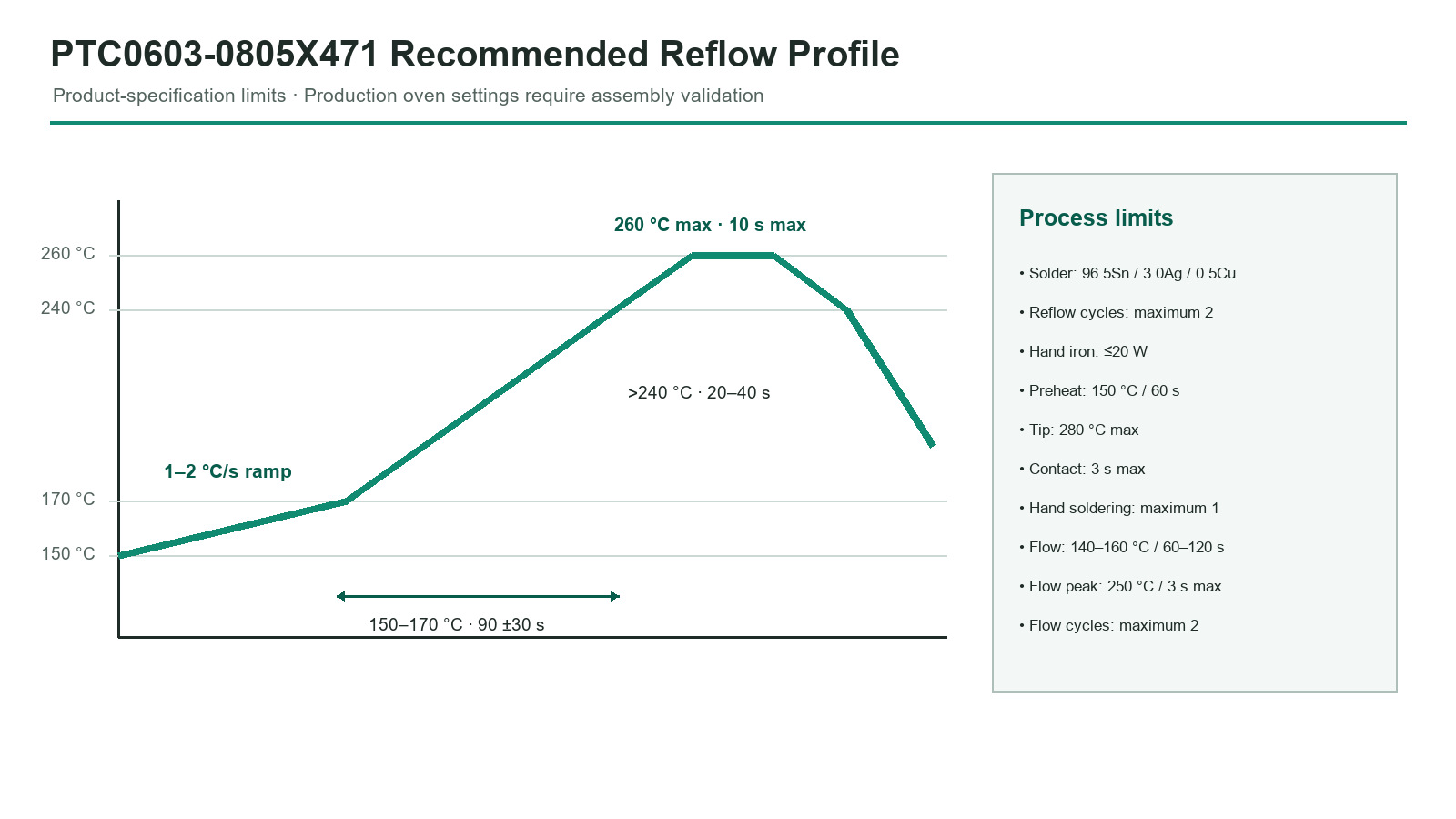
| Reflow | 1–2 °C/s; 150–170 °C for 90 ±30 s; 20–40 s above 240 °C; 260 °C max for 10 s | 2 |
| Flow soldering | 1–2 °C/s; 140–160 °C for 60–120 s; 250 °C max for 3 s | 2 |
| Hand iron | ≤20 W; 150 °C preheat for 60 s; tip ≤280 °C; contact ≤3 s | 1 |
| Parameter | 0603 series | 0805 series |
|---|---|---|
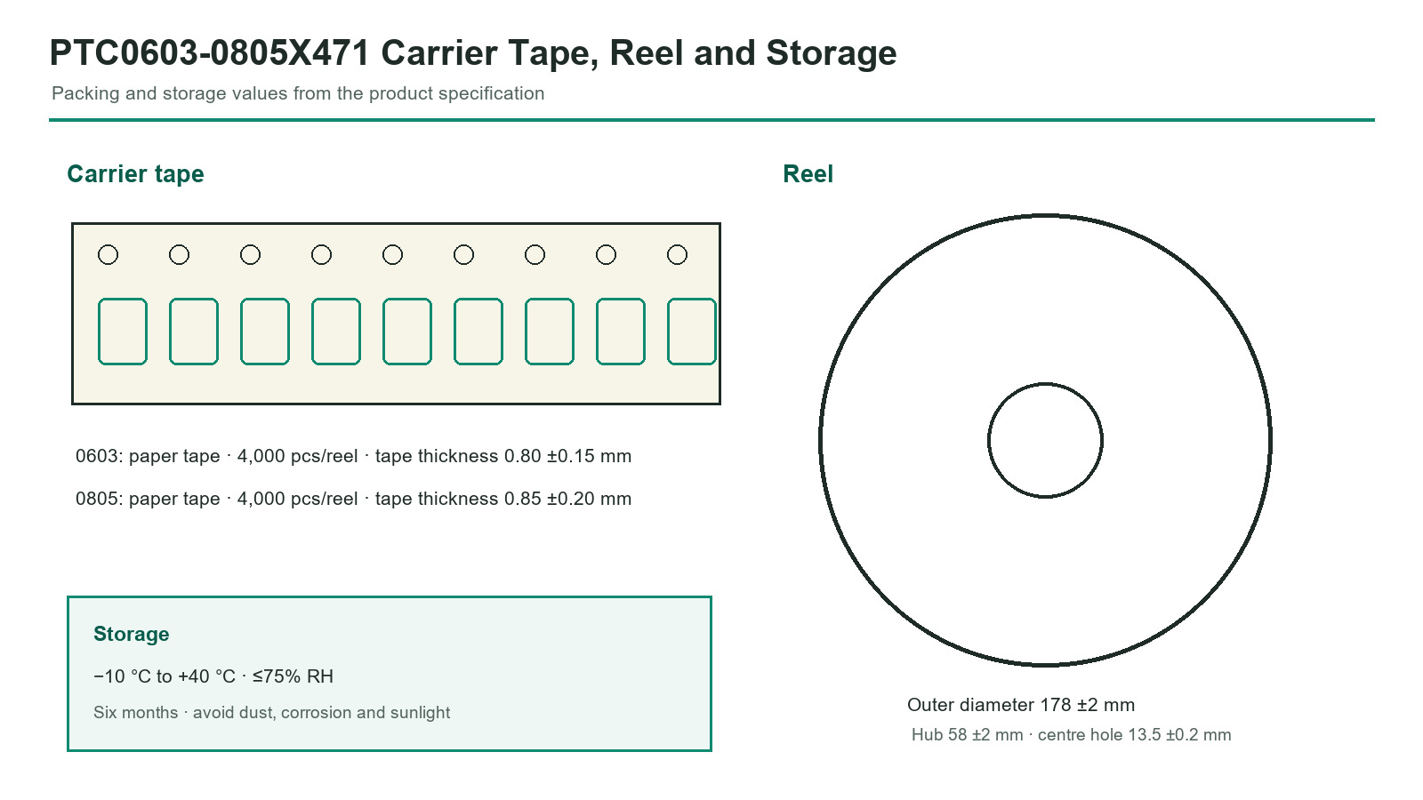
| Carrier material | Paper tape | Paper tape |
| Tape thickness | 0.80 ±0.15 mm | 0.85 ±0.20 mm |
| Quantity per reel | 4,000 | 4,000 |
| Storage temperature | −10 °C to +40 °C | −10 °C to +40 °C |
| Relative humidity | ≤75% RH | ≤75% RH |
| Storage period | 6 months after delivery | 6 months after delivery |
Application Guidance and Design Limitations
The product specification does not grant application-specific or safety certification. The following are potential uses requiring complete electrical, thermal, mechanical, environmental and regulatory qualification.
 PCB overtemperature thresholdMonitor a local PCB hotspot; validate copper heat spreading, mounting offset and trip delay.
 Power stage and motor protectionUse the PTC signal to command an external derating or shutdown function appropriate to the system.
 Compact-device thermal warningQualify enclosure gradients, user-contact conditions, board flex and the required release hysteresis.
 Heater and appliance cutoffImplement independent protection where a single component or control fault could create a hazard.
PTC0603-0805X471 Engineering FAQs
What is the PTC0603-0805X471 Series?
It is a family of passive chip PTC thermistors in 0603 and 0805 packages with 470 Ω nominal R25, 32 V allowable voltage and package-specific temperature codes.
Is this a linear temperature sensor?
No. The intended characteristic is a steep resistance increase around the transition region. Use it for threshold detection with a validated external circuit.
How is Curie temperature defined?
The specification defines it as the temperature at which resistance becomes twice the resistance measured at 25 °C.
Is Curie temperature the same as the 4.7 kΩ sensing temperature?
No. For each listed part, the 4.7 kΩ sensing temperature is higher than the Curie temperature and carries its own ±5 °C tolerance.
Why is a 47 kΩ sensing temperature shown only for PTC0603?
The 0603 electrical table lists both 4.7 kΩ and 47 kΩ sensing temperatures. The 0805 table lists only the 4.7 kΩ point; a 47 kΩ value must not be inferred.
What does the Q code mean?
Q denotes ±5 °C sensing-temperature tolerance in the listed part numbers. Although the identification legend also defines R as ±3 °C, no R-suffixed electrical part number is listed in this PDF.
Can the PTC directly interrupt a load?
No such switching function is specified. Use an external comparator, controller, driver, relay or power-stage response appropriate to the system.
Can 32 V be used as the normal bias voltage?
32 V is the listed allowable voltage. It is not a recommendation to operate at that level. Choose a lower bias consistent with readout margin and self-heating limits.
Can one package be replaced by the other?
Not without redesign and validation. The dimensions, lands, Curie-code coverage, upper working temperatures and available sensing data differ.
How should the parts be stored?
Store at −10 °C to +40 °C and ≤75% RH, away from dust, corrosive atmosphere and sunlight. The specified storage period is six months after delivery.
This page summarizes the NYFEA PTC0603-0805X471 product specification for selection and engineering evaluation. It does not replace the controlled PDF. Confirm the exact listed part number, package, threshold data, ratings, test conditions, dimensions, soldering and final application qualification before release.
