
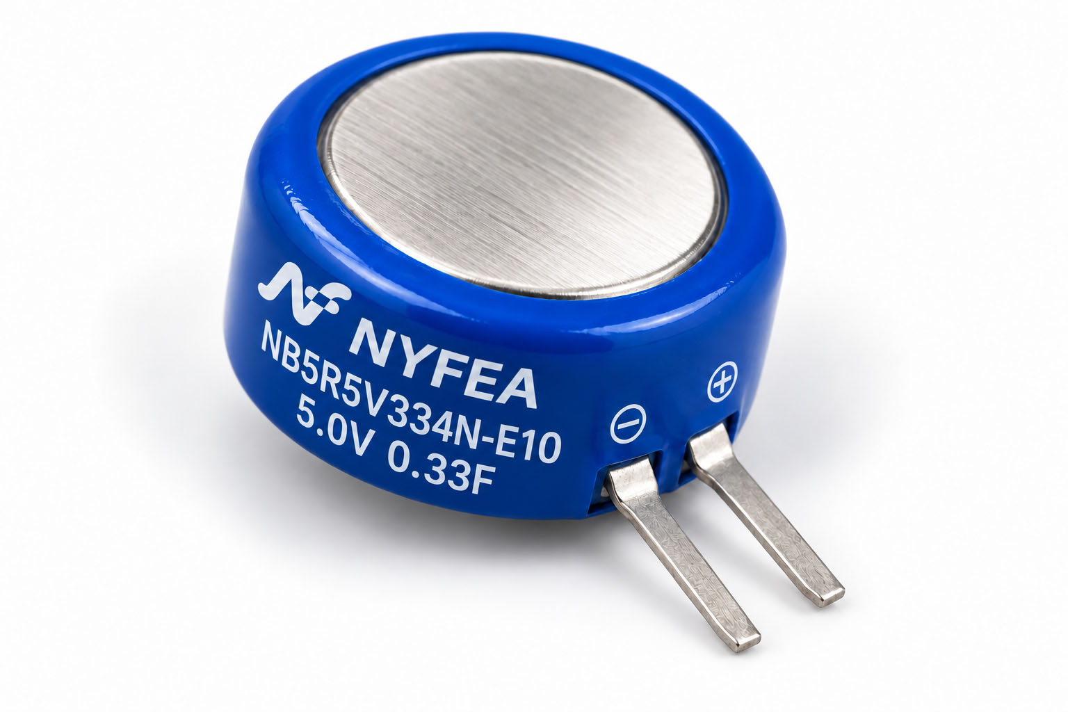
Product Overview and Selection Scope
NB5R5V334N-E10 is a 5.0 V rated, 5.5 V surge, 0.33 F V-type coin supercapacitor with both polarized terminals extending in the same radial direction. Its compact E10 package is intended for RTC backup, low-power state retention and short data-save intervals where PCB area is limited.
This device is polarized and its terminal voltage falls during discharge. Verify the ESR step, capacitance tolerance, load profile, leakage, charging current and minimum system voltage in the complete circuit.
Part-Number Construction
The designation is decoded below using the naming table in the supplied specification.
| Segment | Meaning | Value for this product | Engineering note |
|---|---|---|---|
| NB | Series | Coin-type supercapacitor | Identifies the coin-cell product family. |
| 5R5 | Series voltage code | 5.0 V rated / 5.5 V surge | Use 5.0 V for continuous operation; 5.5 V is the surge limit. |
| V | Terminal format | V-type polarized tabs | Confirm the same-direction terminal geometry, spacing and polarity before PCB release. |
| 334 | Capacitance code | 0.33 F | Nominal capacitance before tolerance and ageing margins. |
| N | Capacitance tolerance | −20% to +80% | Use 0.264 F as the initial minimum for conservative calculations. |
| E10 | Variant code | Compact E10 product variant | Confirm the exact ordering code on the controlled specification. |
Electrical Characteristics
Values below are transcribed from the supplied NYFEA specification. Rated operating voltage and surge voltage are separate limits.
| Parameter | Condition | Specified value | Unit |
|---|---|---|---|
| Rated operating voltage | UR | 5.0 | V |
| Surge voltage | Maximum source-specified surge | 5.5 | V |
| Nominal capacitance | C | 0.33 | F |
| General capacitance tolerance | IEC 62391-1 | −20 to +80 | % |
| Controlled capacitance tolerance | Controlled option | −10 to +20 | % |
| Category temperature range | Ambient | −25 to +70 | °C |
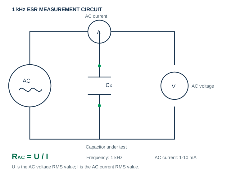
| Maximum ESR | 1 kHz, 10 mA, room temperature | 40 | Ω |
| Leakage current | After 24 h at rated voltage | 5 | µA |
Mechanical Dimensions and Polarity
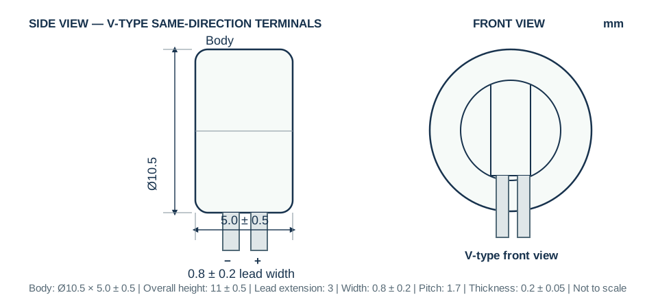
The component uses a polarized V-type coin construction. Both terminals extend in the same radial direction while connecting to opposite electrical poles. Confirm lead spacing, polarity and the full terminal envelope before assembly.
| Dimension | Nominal | Tolerance | Design use |
|---|---|---|---|
| Body diameter | 10.5 mm | Use controlled drawing | Main cylindrical envelope |
| Body thickness | 5.0 mm | ±0.5 mm | Axial package depth |
| Overall body-and-terminal height | 11.0 mm | ±0.5 mm | Reference to terminal datum |
| Lead extension | 3.0 mm | Drawing reference | Terminal projection below the body datum |
| Tab thickness | 0.2 mm | ±0.05 mm | Terminal cross-section |
| Lead width / pitch | 0.8 / 1.7 mm | ±0.2 / drawing reference | Use the controlled drawing for PCB-hole geometry |
Reliability and Endurance
| Test | Source condition | Capacitance requirement | ESR requirement |
|---|---|---|---|
| Load life | 5.0 V at +70 ±2 °C for 1000 h | Decrease ≤30% from initial | ≤4 × specified value |
| Temperature cycling | Five cycles: −25 °C → room temperature → +70 °C → room temperature | Decrease ≤30% from initial | ≤3 × specified value |
| Storage life | Source-defined 1000 h condition within −25 to +70 °C | Decrease ≤30% from initial | ≤4 × initial |
| Cycle life | 500,000 constant-current cycles between specified and half-specified voltage at +25 °C | Within ±30% of initial | ≤3 × initial |
Capacitance and ESR Test Methods
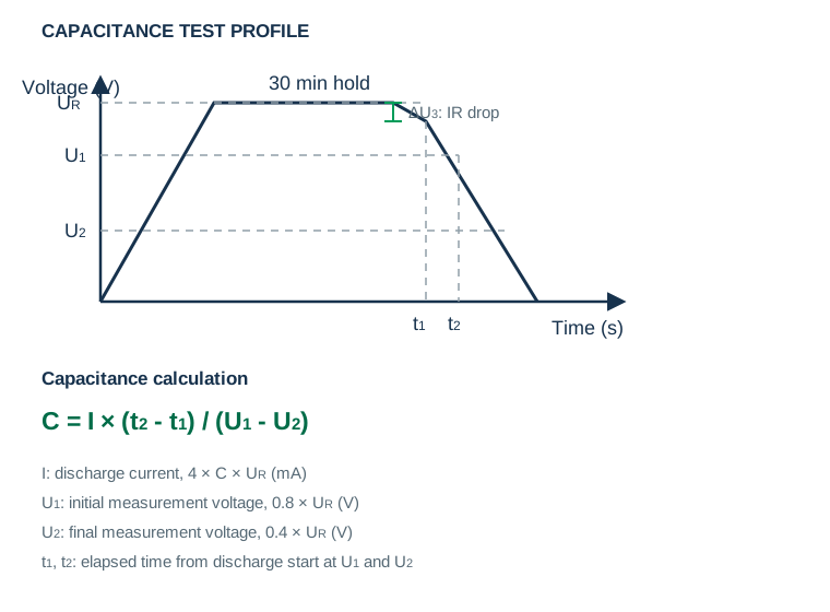
For capacitance measurement, charge the device to rated voltage for 30 minutes and discharge it at the prescribed constant current. ESR is measured using the specified 1 kHz AC method.
Hold-Up, Leakage and Energy Calculations
Estimate the usable interval from the allowable voltage window and load current, then subtract the immediate ESR voltage step. For leakage-current testing, fully discharge the device for 1–24 hours, apply rated voltage for 72 hours, and then measure the current.
PCB Mounting, Soldering and Handling
Assembly and environmental conditions directly affect reliability. Apply the following source-specification precautions during layout and process qualification.
If devices are connected in series, implement voltage balancing and obtain NYFEA application guidance. Also validate hole size, lead pitch, cleaning chemistry, polarity inspection and mechanical support before release.
Application Guidance and Design Limitations
The applications below are engineering use cases consistent with a compact 5.0 V rated, 0.33 F backup component. They are not end-product certification claims.
 RTC BackupMaintain timekeeping through a brief loss of the main supply.
 Memory RetentionSupport low-power state preservation and orderly data save.
 Smart Meter Data SaveProvide a short window for nonvolatile recording after mains loss.
 Compact Control NodesBridge short interruptions after validating the source-listed current limit.
 Wireless Sensor BackupMaintain low-power state between supply events after circuit validation.
The source specification does not claim automotive, medical, functional-safety, life-support or fault-tolerant qualification. Confirm all mandatory standards for the end product.
NB5R5V334N-E10 Engineering FAQs
What are the rated voltage and nominal capacitance?
The rated operating voltage is 5.0 V, the surge voltage is 5.5 V, and the nominal capacitance is 0.33 F.
What capacitance tolerance is specified?
The supplied specification states −20% to +80%, corresponding to an initial range of 0.264 F to 0.594 F before additional temperature and ageing allowances.
What is the maximum ESR?
The maximum ESR is 40 Ω at 1 kHz and 10 mA at room temperature.
What is the operating temperature range?
The specified operating range is −25 °C to +70 °C.
What are the package dimensions and terminal arrangement?
The source drawing specifies an Ø10.5 mm body with 5.0 ±0.5 mm thickness. The compact E10 V-type terminals extend in the same radial direction; use the controlled drawing for the complete footprint.
Is the component polarized?
Yes. Match the negative marking to the PCB polarity before soldering.
Can it be used as a direct battery replacement?
No. A supercapacitor has continuous voltage decay and an ESR-related voltage step. Validate the load current, minimum system voltage, usable energy and required hold-up time.
What is the difference between rated and surge voltage?
Use 5.0 V as the continuous rated operating voltage. The 5.5 V value is the source-specified surge voltage, not the continuous rating.
Which document controls production decisions?
The supplied NB5R5V334N-E10 PDF and the current NYFEA-controlled revision remain the design authority.
This page summarizes the supplied NB5R5V334N-E10 product specification for component evaluation. Confirm the current revision, dimensions, polarity, rated-versus-surge voltage, test conditions, assembly process and qualification requirements before production release.