
Product Overview and Selection Scope
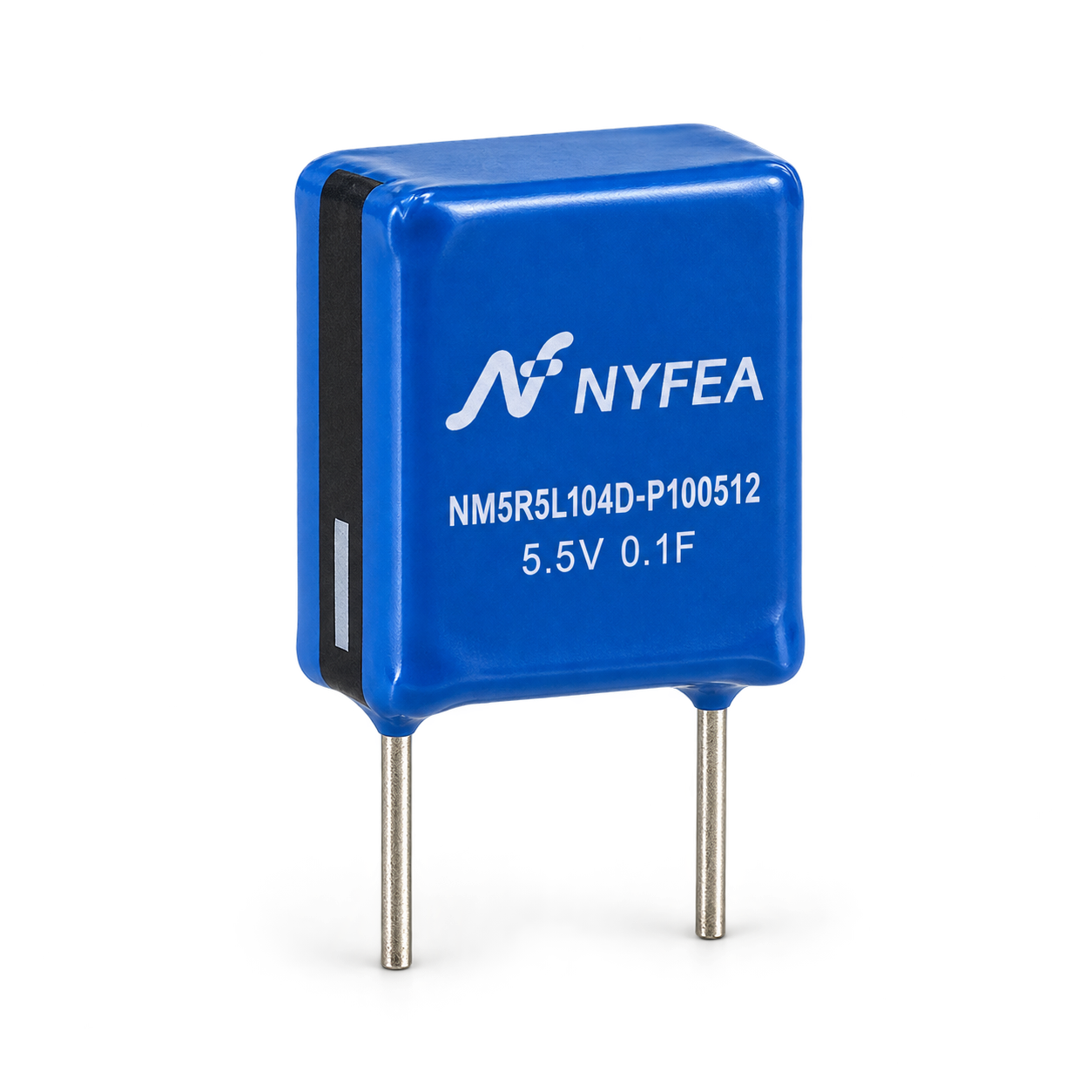
NM5R5L104D-P100512 is a 5.5 V combined supercapacitor with a 0.1 F nominal capacitance and radial leads. It is intended for low-power energy storage where a short hold-up interval, state retention or controlled backup discharge is required.
A supercapacitor is not a regulated power source. Validate voltage decay, ESR drop, charging current, reverse polarity risk, temperature, leakage and the minimum load operating voltage in the final circuit.
Part-Number Construction
The supplied specification identifies the construction code as follows. This breakdown is included for engineering interpretation and does not replace an approved ordering record.
| Segment | Meaning | Value for this product | Engineering note |
|---|---|---|---|
| NM | Product series | Combined supercapacitor | Confirm current series definition in the controlled catalog. |
| 5R5 | Rated voltage code | 5.5 V | Do not exceed the rated voltage in service. |
| 104 | Capacitance code | 0.1 F | Nominal value before tolerance is applied. |
| D | Capacitance tolerance | 0% to +100% | Use the minimum capacitance for worst-case hold-up calculations. |
| 10 / 05 / 12 | Body dimensions | 10 / 5 / 12 mm | W / D / L nominal dimensions. |
Electrical Characteristics
Values below are transcribed from the supplied product specification. Units and test conditions must remain attached to the parameter when the device is evaluated.
| Parameter | Symbol / condition | Specified value | Unit |
|---|---|---|---|
| Rated voltage | UR | 5.5 | V |
| Nominal capacitance | C | 0.1 | F |
| Capacitance tolerance | At specified test conditions | 0 to +100 | % |
| Operating temperature | Ambient range | −40 to +65 | °C |
| Maximum equivalent series resistance | RAC, 1 kHz | 1400 | mΩ |
| Maximum leakage current | After 72 h at rated voltage | 0.002 | mA |
| Maximum working current | ΔT = 15 °C | 0.1 | A |
| Maximum peak current | Short-duration peak | 0.25 | A |
| Maximum stored energy | Source value | 0.42 × 10⁻³ | Wh |
| Energy density | Source value | 0.525 | Wh/kg |
| Power density | Source value | 1226 | W/kg |
Calculate hold-up time with minimum capacitance, maximum ESR, leakage, load tolerance and the lowest allowable system voltage. Do not use the nominal 0.1 F value alone for production sign-off.
Mechanical Dimensions and Polarity
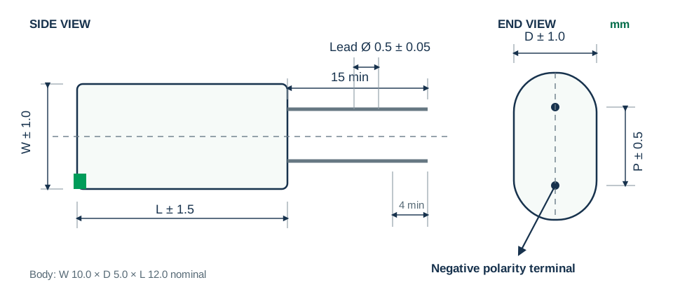
The product is polarized. Confirm the negative marking before assembly and keep the body and leads free from bending loads after soldering.
| Dimension | Nominal | Tolerance | Design use |
|---|---|---|---|
| W | 10.0 mm | ±1.0 mm | Body width |
| D | 5.0 mm | ±1.0 mm | Body depth |
| L | 12.0 mm | ±1.5 mm | Body length |
| φd | 0.5 mm | ±0.05 mm | Lead diameter |
| P | 7.3 mm | ±0.5 mm | Lead pitch |
Reliability and Endurance
The source specification defines pass limits through capacitance change and ESR multiplication. These tests are qualification references, not permission to operate continuously at every boundary condition.
| Test | Source condition | Capacitance change | ESR limit |
|---|---|---|---|
| Cycle life | 500,000 charge-discharge cycles at 25 °C between rated and half-rated voltage using constant current | ≤ 30% from initial | ≤ 4 × initial |
| Storage life | 1000 h, no load, within the upper rated temperature range | Per specified post-test limit | Per specified post-test limit |
| Endurance | 1000 h at rated voltage within the upper rated temperature range | ≤ 30% from initial | ≤ 4 × initial |
| Life assessment | 10 years at rated voltage and +25 °C | ≤ 30% from initial | ≤ 4 × initial |
| Temperature characteristic | −40 °C, +25 °C and +65 °C | ≤ 30% from initial | ≤ 2 × initial |
| Humidity resistance | +40 ±2 °C, 90–95% RH, 240 h | ≤ 30% from initial | ≤ 2 × initial |
Capacitance and ESR Test Methods
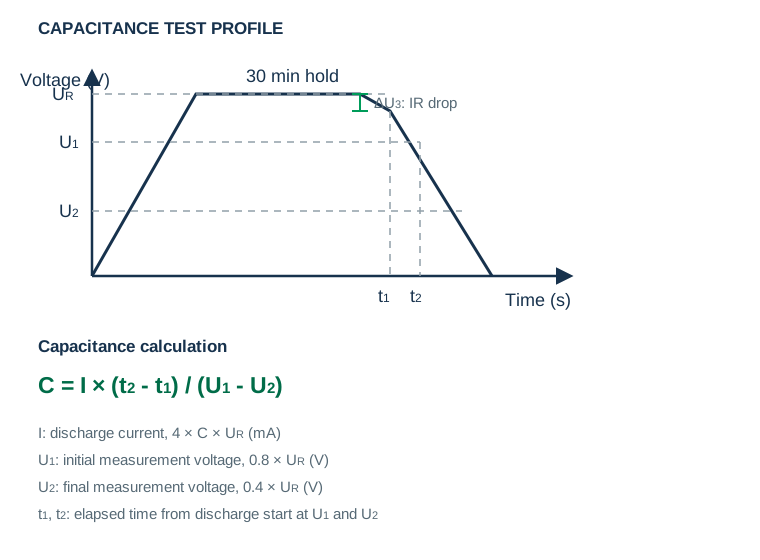
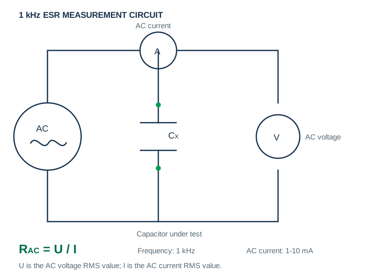
Capacitance is determined from a controlled discharge interval after charging to rated voltage. ESR is measured with the specified 1 kHz AC method.
Leakage, Current and Energy Calculations
Before leakage-current measurement, discharge the capacitor for 1 to 24 hours. Apply rated voltage with constant voltage for 72 hours, then measure leakage current.
PCB Mounting, Soldering and Handling
Assembly conditions directly affect life and reliability. The following points summarize the handling cautions in the supplied specification.
Verify hole size, lead pitch, creepage, polarity marking, cleaning chemistry, solder profile and mechanical support with the assembler before release.
Application Guidance and Design Limitations
These are engineering use contexts inferred from the product's 5.5 V, 0.1 F backup characteristics. They are not end-product qualification claims. Each icon is a separate asset and corresponds directly to the application copy below it.
 RTC BackupMaintain timekeeping during a short loss of the main supply.
 Memory RetentionSupport orderly state retention in low-power electronics.
 Smart Meter Hold-UpProvide brief energy support for data capture or shutdown.
 Industrial ControlBridge short supply interruptions in low-power control nodes.
 Wireless Sensor NodesBuffer low-duty-cycle backup loads after system validation.
The supplied specification does not establish automotive, medical, functional-safety, life-support or fault-tolerant qualification. Do not use the application list as certification evidence.
NM5R5L104D-P100512 Engineering FAQs
What are the rated voltage and nominal capacitance?
The rated voltage is 5.5 V and the nominal capacitance is 0.1 F.
What capacitance tolerance is specified?
The supplied specification states 0% to +100%. Use 0.1 F as the minimum nominal basis before aging and temperature margins.
What is the maximum ESR?
The maximum equivalent series resistance is 1400 mΩ using the specified 1 kHz AC method.
What is the operating temperature range?
The specified operating range is −40 °C to +65 °C.
Is the device polarized?
Yes. The negative terminal is identified in the mechanical drawing and polarity must be checked before assembly.
What are the nominal body dimensions and lead pitch?
The body is 10.0 × 5.0 × 12.0 mm nominal, with a 7.3 mm nominal lead pitch.
Can this device be treated as a battery replacement?
No. It has voltage decay and ESR drop during discharge. Confirm load current, minimum system voltage, leakage and required hold-up time.
Which document controls production decisions?
The supplied NM5R5L104D-P100512 PDF and the current NYFEA-controlled revision remain the design authority.
This page summarizes the supplied NM5R5L104D-P100512 product specification for component evaluation. Confirm the current revision, dimensions, polarity, test conditions, assembly process and qualification requirements before production release.