
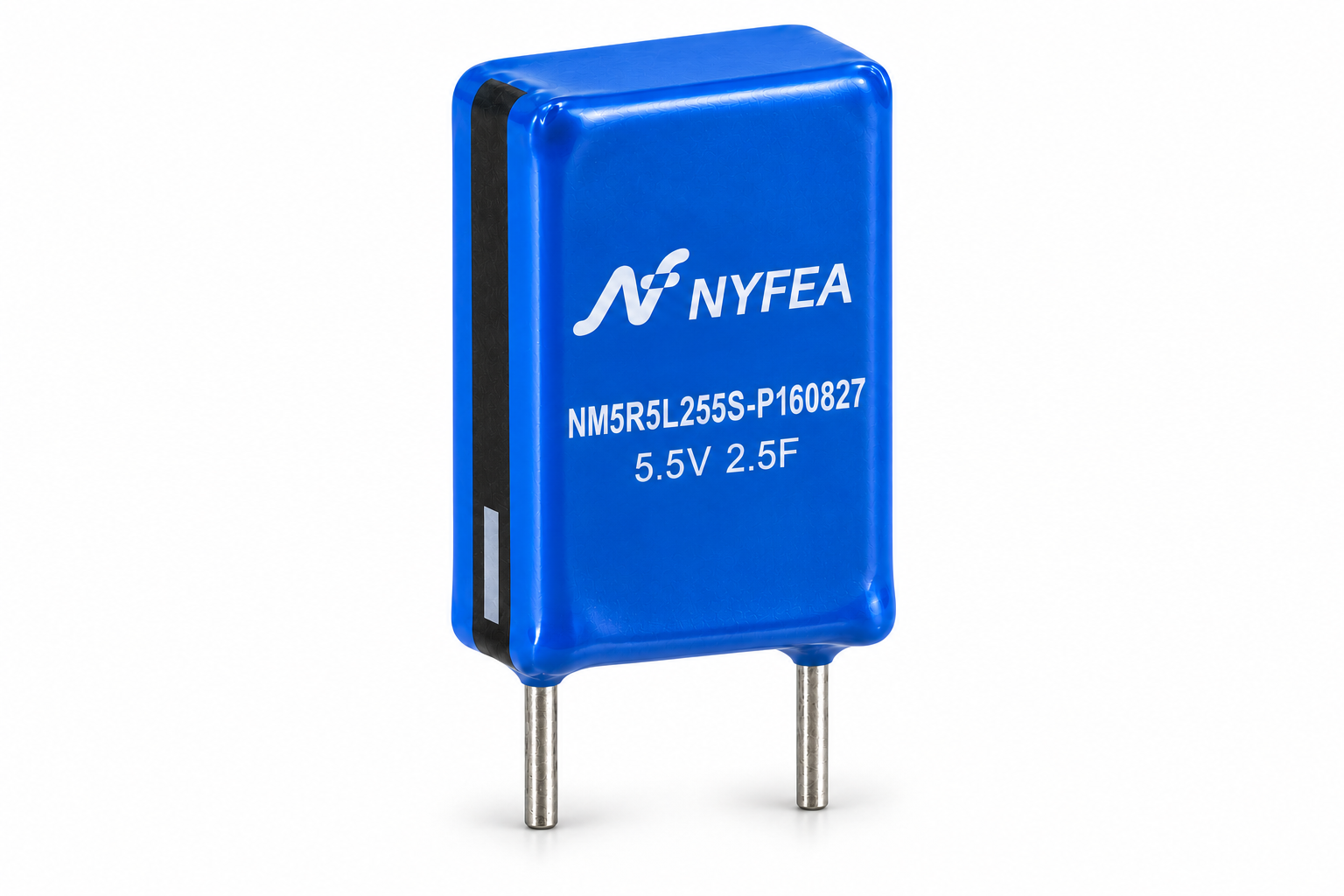
Product Overview and Selection Scope
NM5R5L255S-P160827 is a 5.5 V, 2.5 F combined supercapacitor with wire leads. Its higher stored energy and source-defined current capability support validated backup intervals, data capture and controlled shutdown loads.
This device is polarized and its terminal voltage falls during discharge. Verify the ESR step, capacitance tolerance, load profile, leakage, charging current and minimum system voltage in the complete circuit.
Part-Number Construction
The designation is decoded below using the naming table in the supplied specification.
| Segment | Meaning | Value for this product | Engineering note |
|---|---|---|---|
| NM | Series | Combined supercapacitor module | Distinguishes the module construction in the source naming system. |
| 5R5 | Rated-voltage code | 5.5 V | Do not exceed the rated voltage. |
| L | Terminal format | Wire lead | Confirm footprint and polarity before PCB release. |
| 255 | Capacitance code | 2.5 F | Nominal capacitance before tolerance and ageing margins. |
| S | Capacitance tolerance | −20% to +50% | Use 2.0 F as the initial minimum for conservative calculations. |
| P | Function code | Power type | Source naming classification; not a system-level power rating. |
| 16 / 08 / 27 | Body size codes | 16 / 8 / 27 mm | Nominal W / D / L dimensions. |
Electrical Characteristics
Values are transcribed from the supplied specification. Keep the stated units and test conditions attached to each parameter during comparison and design review.
| Parameter | Condition | Specified value | Unit |
|---|---|---|---|
| Rated voltage | UR | 5.5 | V |
| Nominal capacitance | C | 2.5 | F |
| Capacitance tolerance | Initial value | −20 to +50 | % |
| Operating temperature | Ambient range | −40 to +70 | °C |
| Maximum AC equivalent series resistance | RAC, 1 kHz | 180 | mΩ |
| Maximum DC resistance | RDC | 400 | mΩ |
| Maximum leakage current | After 72 h at rated voltage | 0.015 | mA |
| Rated current | At 25 °C | 1.15 | A |
| Maximum peak current | Source-specified peak value | 3.44 | A |
| Maximum stored energy | 0.5CUR2 / 3600 | 0.0105 | Wh |
| Energy density | Source value | 2.63 | Wh/kg |
| Power density | Source-listed value; unit requires confirmation | 2.27 | W/kg |
| Typical product mass | Source value | 4.0 | g |
The supplied PDF lists power density as 2.27 W/kg. Applying the formula printed in the same table to 5.5 V, 400 mΩ and 4.0 g gives approximately 2.27 kW/kg. This page preserves the source value; confirm the intended unit with NYFEA before using it in comparisons or published claims.
Mechanical Dimensions and Polarity
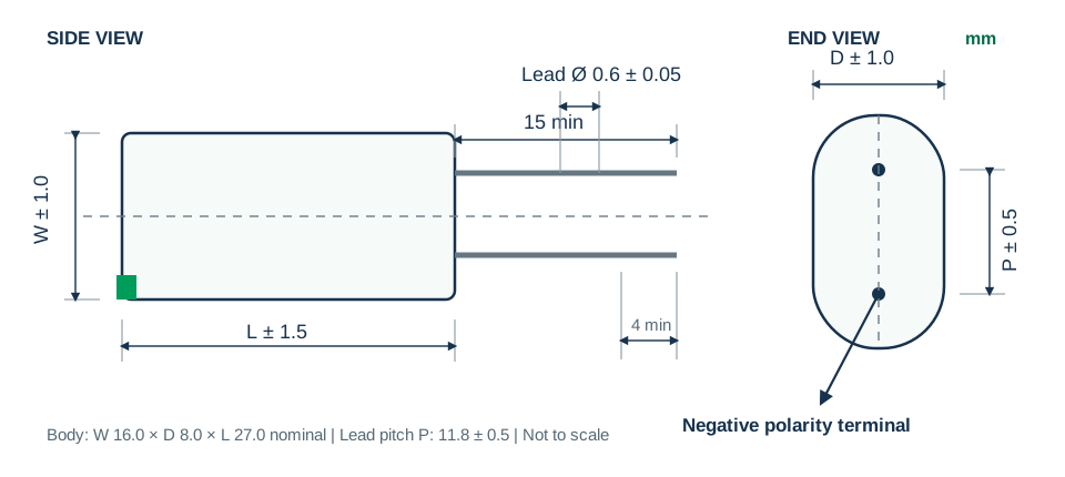
The package is polarized. The marked negative terminal must match the PCB polarity, and the leads must not be used to absorb mechanical stress.
| Dimension | Nominal | Tolerance | Design use |
|---|---|---|---|
| W | 16.0 mm | ±1.0 mm | Body width |
| D | 8.0 mm | ±1.0 mm | Body depth |
| L | 27.0 mm | ±1.5 mm | Body length |
| φd | 0.6 mm | ±0.05 mm | Lead diameter |
| P | 11.8 mm | ±0.5 mm | Lead pitch |
Reliability and Endurance
The specification defines post-test limits for capacitance change and internal resistance. These are qualification conditions, not continuous-use permissions at every limit.
| Test | Source condition | Capacitance change | Resistance limit |
|---|---|---|---|
| Cycle life | 500,000 constant-current cycles at 25 °C between rated voltage and half-rated voltage | ≤ 30% from initial | ≤ 4 × initial |
| Storage life | 1000 h with no load at the upper rated-temperature condition | ≤ 30% from initial | ≤ 4 × initial |
| Endurance | 1000 h at rated voltage at the upper rated-temperature condition | ≤ 30% from initial | ≤ 4 × initial |
| Life assessment | 10 years at 25 °C and rated voltage | ≤ 30% from initial | ≤ 4 × initial |
| Temperature characteristic | −40 °C, +25 °C and +70 °C | ≤ 30% from initial | ≤ 3 × initial |
| Damp-heat storage | +40 ±2 °C, 90–95% RH, 240 h | ≤ 30% from initial | ≤ 2 × initial |
Capacitance and ESR Test Methods
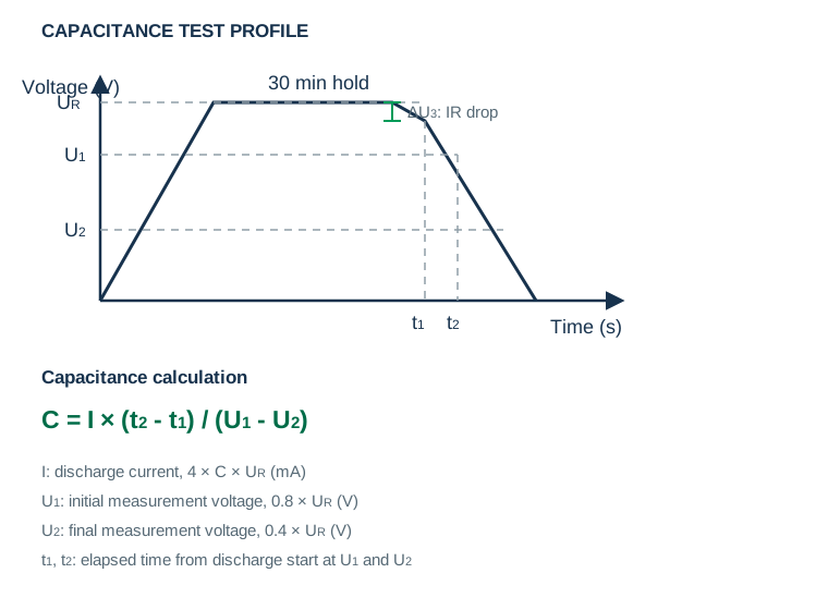
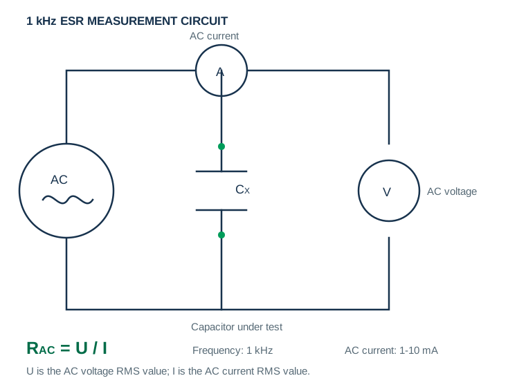
For capacitance measurement, charge the device to rated voltage for 30 minutes and discharge it at the prescribed constant current. ESR is measured using the specified 1 kHz AC method.
Hold-Up, Leakage and Energy Calculations
Estimate the usable interval from the allowable voltage window and load current, then subtract the immediate ESR voltage step. For leakage-current testing, fully discharge the device for 1–24 hours, apply rated voltage for 72 hours, and then measure the current.
PCB Mounting, Soldering and Handling
Assembly and environmental conditions directly affect reliability. Apply the following source-specification precautions during layout and process qualification.
If devices are connected in series, implement voltage balancing and obtain NYFEA application guidance. Also validate hole size, lead pitch, cleaning chemistry, polarity inspection and mechanical support before release.
Application Guidance and Design Limitations
The applications below are engineering use cases consistent with a 5.5 V, 2.5 F backup component. They are not end-product certification claims.
 RTC and Controller BackupPreserve timekeeping or controller state through a supply interruption.
 Data RetentionProvide time for nonvolatile data save before a controlled shutdown.
 Smart Meter Hold-UpSupport last-gasp data capture or communication after mains loss.
 Industrial Control Ride-ThroughBridge brief brownouts in validated monitoring and control nodes.
 Wireless Sensor BufferSupply validated short current bursts in duty-cycled sensing systems.
The source specification does not claim automotive, medical, functional-safety, life-support or fault-tolerant qualification. Confirm all mandatory standards for the end product.
NM5R5L255S-P160827 Engineering FAQs
What are the rated voltage and nominal capacitance?
The rated voltage is 5.5 V and the nominal capacitance is 2.5 F.
What capacitance tolerance is specified?
The supplied specification states −20% to +50%, corresponding to an initial range of 2.0 F to 3.75 F before additional temperature and ageing allowances.
What resistance limits are specified?
Maximum AC ESR is 180 mΩ at 1 kHz, and maximum DC resistance is 400 mΩ.
What is the operating temperature range?
The specified operating range is −40 °C to +70 °C.
What are the package dimensions and lead pitch?
The nominal body is 16.0 × 8.0 × 27.0 mm, with an 11.8 mm nominal lead pitch and 0.6 mm nominal lead diameter.
Is the component polarized?
Yes. Match the negative marking to the PCB polarity before soldering.
Can it be used as a direct battery replacement?
No. A supercapacitor has continuous voltage decay and an ESR-related voltage step. Validate the load current, minimum system voltage, usable energy and required hold-up time.
Why should the power-density unit be confirmed?
The source table states 2.27 W/kg, while its printed formula and values imply approximately 2.27 kW/kg. Confirm the intended unit with NYFEA before publication or comparison.
Which document controls production decisions?
The supplied NM5R5L255S-P160827 PDF and the current NYFEA-controlled revision remain the design authority.
This page summarizes the supplied NM5R5L255S-P160827 product specification for component evaluation. Confirm the current revision, dimensions, polarity, resistance values, power-density unit, test conditions and assembly process before production release.