CLRC663 ATQA but No UID: STM32 SPI Debug Guide
If your STM32 can read CLRC663 registers and receive ATQA, but the next anticollision request returns no usable UID bytes, start here. Follow the first failed exchange from SPI writes to receiver status, then check SELECT and SAK.
QUICK ANSWER
When CLRC663 returns ATQA but no UID, first check the transition from REQA to anticollision. REQA uses seven bits; the initial CL1 request uses two complete bytes, 0x93 0x20. Restore byte-aligned transmission without clearing DataEn, disable transmit CRC generation and receive CRC checking for this exchange, and inspect the captured result before retrying. Repeatable ATQA is a useful starting point, not proof of adequate RF margin for every frame.
An Access Reader That Detects a Card but Cannot Read Its UID
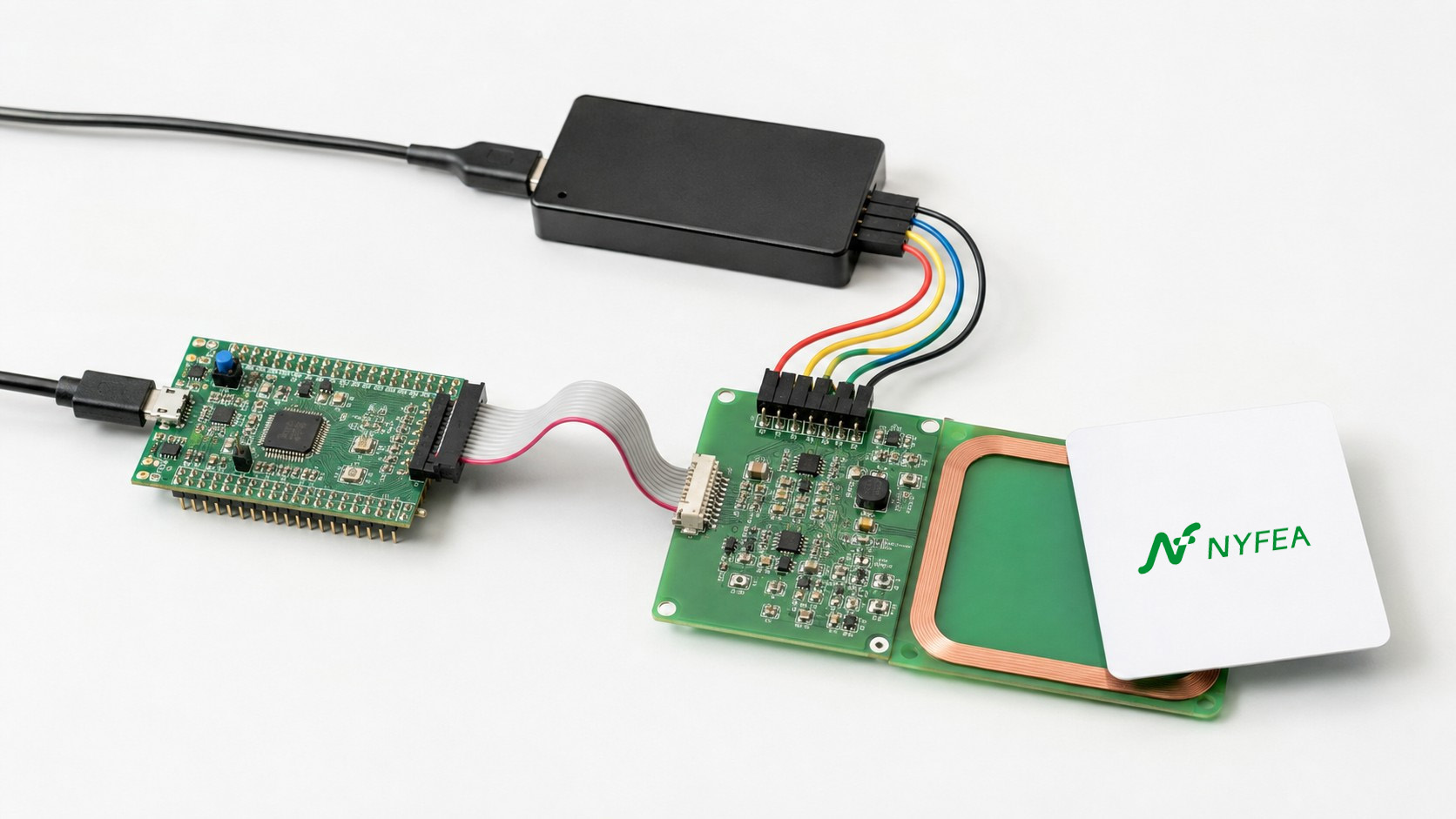
Consider an STM32-based access-control reader during board bring-up. With one ISO/IEC 14443 Type A card held at a fixed position, register reads are stable and REQA returns two ATQA bytes. The application still reports “no UID” after the first anticollision request. At this point, changing antenna components would introduce another variable before the failed exchange has been explained.
Example scope: this is an illustrative application scenario, not a NYFEA customer deployment or a measured test report. The worked example below examines one specific configuration mistake and shows how to test that explanation without inventing a successful result.
93 20.ATQA is not a UID. It is the response to initial polling; anticollision and SELECT are separate exchanges. If five valid anticollision bytes are already available but SAK is missing, skip to the SELECT checks in the table below.
A related NXP Community discussion reports difficulty progressing from REQA to anticollision and selection. It provides symptom context, not a verified root cause for this illustrative scenario.
ATQA but No UID: Find the First Failed Exchange
Swipe to view all columns →
| Observed result | Highest-priority checks | Do not change first |
|---|---|---|
| No ATQA after REQA | RF field, Type A profile, seven-bit REQA, power rails, antenna connection and receiver path | UID cascade code |
ATQA received; FIFO empty after 93 20 | Actual TxDataNum readback, FIFO writes, DataEn, IRQ handling, timeout and premature Idle | LPCD thresholds |
| Partial bytes or invalid BCC | RxBitCtrl alignment, RxColl validity, collision position, FIFO read length and bit-prefix handling | Blindly increasing RF power |
| Five anticollision bytes; no SAK | NVB 0x70, transmitted UID/CT bytes, BCC, CRC_A configuration and SELECT response timeout | Repeating REQA indefinitely |
| Four-byte UID works; seven-byte UID fails | Cascade tag removal, SAK cascade bit, CL2 command 0x95 and final UID assembly | SPI clock rate |
| One card works; two cards are unstable | RxColl, first collision position, chosen branch bit, updated NVB and repeatable prefix construction | Single-card-only tuning |
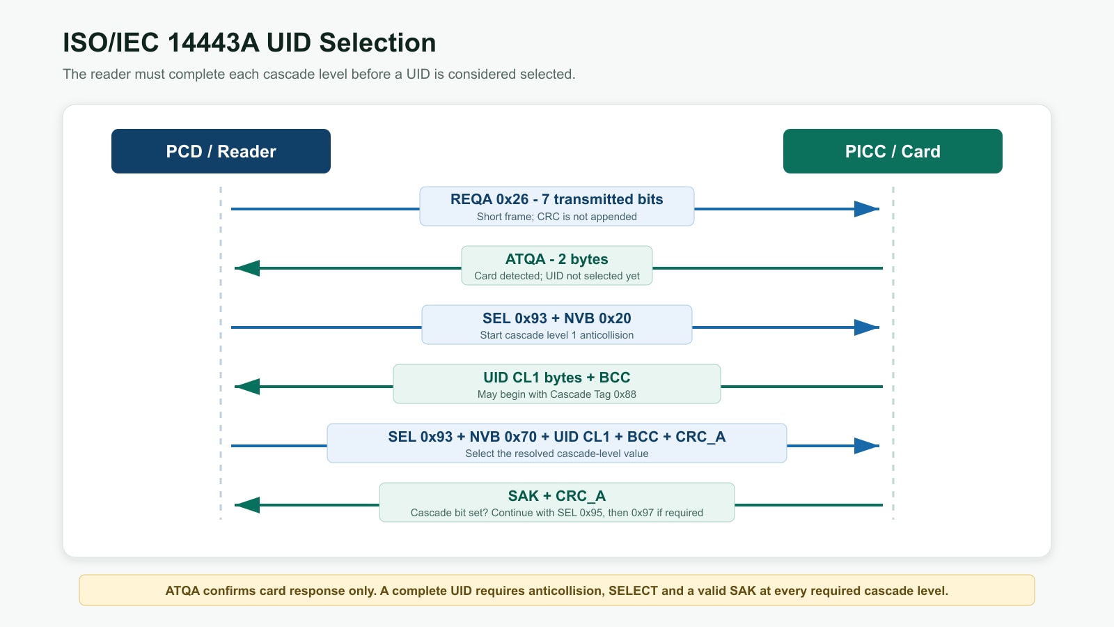
What REQA, Anticollision, SELECT and SAK Each Do
Swipe to view all columns →
| Stage | Reader frame over the air | Expected card response over the air | What the result proves |
|---|---|---|---|
| Polling | REQA 0x26, seven valid bits, no CRC_A | Two-byte ATQA | At least one idle card responded to the Type A short frame. |
| Anticollision CL1 | 0x93 0x20 | Four cascade-level bytes plus BCC, unless a bit collision must be resolved | The host can receive a cascade-level value and inspect collision state. |
| Select CL1 | 0x93 0x70 + five bytes + CRC_A | SAK + CRC_A | The chosen cascade-level value was selected. |
| Additional level | 0x95 for CL2; 0x97 for CL3 | Next UID fragment and BCC, then SAK | The host assembles a seven- or ten-byte UID. |
SEL + 0x20 is five bytes: four cascade-level bytes followed by BCC. If the first byte is the cascade tag 0x88, it is not part of the final UID.Check the CLRC663 and STM32 Command Flow
The examples use driver-neutral pseudocode, not a complete STM32 HAL driver. Adapt each operation to your driver and device revision. Bit-field setters must preserve unrelated register bits; CRC helpers must change the enable state without overwriting the Type A preset.
1. Start from a known Type A state
- Read the documented device version and confirm stable results across repeated SPI reads.
- Apply the documented ISO 14443A 106 kbit/s protocol profile for both receive and transmit paths.
- After saving the previous result, set the reader idle, flush FIFO, clear relevant IRQ flags and configure a receive timeout plus a host-side deadline.
- Do not combine protocol bring-up with antenna retuning or LPCD changes.
2. Send REQA as a seven-bit short frame
uint8_t reqa = 0x26;

reader_idle();
flush_fifo();
clear_irq0_irq1();
configure_timeout();

disable_tx_crc();
disable_rx_crc();
set_tx_data_enabled(true);
set_tx_last_bits(7);         // REQA is a seven-bit short frame
set_rx_align(0);
set_rx_multiple(false);

write_fifo(&reqa, sizeof reqa);
start_transceive();
event = wait_for_exchange_event(host_deadline);
result = capture_exchange_result(event);
REQA does not carry CRC_A, and ATQA must be received without expecting CRC_A. NXP's AN12657, section 4.1, gives the corresponding polling configuration. Accept ATQA only after checking the receive status and two-byte payload; a wait function returning is not a success indication.
For repeated tests, also control the card state. A card in HALT does not answer REQA; use the appropriate wake-up or field-reset sequence before comparing polling attempts.
3. Start cascade-level 1 anticollision
uint8_t anticoll_cl1[2] = { 0x93, 0x20 };

reader_idle();
flush_fifo();
clear_irq0_irq1();
configure_timeout();

disable_tx_crc();
disable_rx_crc();

set_tx_data_enabled(true);
set_tx_last_bits(0);         // Full final byte; preserve DataEn
set_rx_align(0);             // Initial NVB 0x20 round starts byte-aligned
set_values_after_collision(false);
set_no_collision_error(false);
set_rx_multiple(false);

write_fifo(anticoll_cl1, sizeof anticoll_cl1);
start_transceive();
event = wait_for_exchange_event(host_deadline);
result = capture_exchange_result(event);

/* A completed wait is not necessarily a valid response. */
if (result.aborted || result.truncated || result.has_frame_error) {
    report_failure(result);
} else if (result.error_coll_det) {
    inspect_collision_validity_and_resolve_branch(result);
} else if (result.rx_complete &&
           result.fifo_len == 5 &&
           result.rx_last_bits == 0 &&
           bcc_matches(result.rx_data)) {
    save_cascade_level_bytes(result.rx_data);
} else {
    report_unusable_response(result);
}
Transmit framing: TxDataNum.DataEn and TxLastBits are separate fields. For CL1, set TxLastBits=0 to send a complete final byte and keep DataEn=1. With the other bits clear, the REQA-to-CL1 change is 0x0F → 0x08, not 0x0F → 0x00. Preserve KeepBitGrid if your protocol configuration uses it. See the CLRC663 data sheet, TxDataNum register.
CRC and reception: disable transmit CRC generation and receive CRC checking for initial anticollision. Set RxAlign=0 for the initial NVB 0x20 request. Keep ValuesAfterColl=0, NoColl=0 and RxMultiple=0. Read Error.CollDet explicitly; a collision must not be treated as a valid five-byte UID response.
Helper contract: wait_for_exchange_event() observes the relevant receive, error, idle and timer events with a host-side deadline; it returns a reason, not a pass/fail verdict. capture_exchange_result() first saves IRQ0/IRQ1, Error, Status, RxBitCtrl and RxColl. On timeout or an error while reception is still active, it records an aborted exchange and stops the command before reading a stable FIFO length and bounded payload. It must report truncation, preserve the original failure status, and never clear IRQs or flush FIFO before saving the evidence.
RxColl.CollPos only if CollPosValid=1. Select a branch bit, append the known UID prefix, update NVB and configure TxLastBits and RxAlign for the next partial-bit round. If the position is invalid, do not invent a branch from that register value. It is not a complete multi-card collision-resolution loop.4. Check BCC, then SELECT the cascade-level value
For an uncollided five-byte response, XOR the four cascade-level bytes and compare the result with BCC. Then send:
Enable CRC_A generation for SELECT and CRC_A checking for its response. If hardware appends CRC_A, do not also place a second CRC in the transmit FIFO. Check the receive status before accepting SAK; distinguish the over-the-air SAK-plus-CRC frame from the payload your driver exposes after CRC handling.
If the SAK cascade bit is set, retain the UID bytes and continue with 0x95 for CL2. Use 0x97 for CL3 when required. Exclude cascade tags and BCC bytes from the final UID.
Use the Logic Analyzer to Connect SPI Activity to Protocol State
Capture NSS, SCK, MOSI, MISO and the reader IRQ signal. Start by checking transaction boundaries and decoded bytes. SPI writes show what the host sent to the reader; they do not, by themselves, prove what the antenna transmitted.
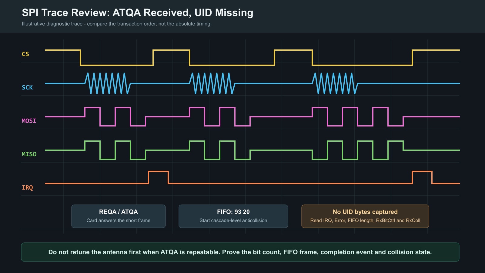
Separate SPI register writes from the RF command
For a CLRC663 SPI write, the first byte is the register address shifted left by one bit, with bit 0 cleared. The FIFOData register is 0x05; its SPI write-address byte is therefore 0x0A. The examples below show MOSI bytes in hexadecimal, following NXP AN12657, section 2.1.
| Operation | MOSI bytes during one NSS-low interval | How to interpret it |
|---|---|---|
| Load REQA into FIFO | 0A 26 | 0A addresses FIFOData; only 26 is the protocol payload. |
| Load initial CL1 request into FIFO | 0A 93 20 | 93 20 is the two-byte RF request. Do not transmit the SPI address byte over the air. |
| Start Transceive | 00 07 | Write command value 07 to Command register 00 in a separate SPI transaction. |
Keep NSS low for each complete transaction and return it high between commands. These are individual write examples, not an initialization script: configure framing, clear stale state and load the intended FIFO payload before starting Transceive. Check the SPI mode and timing limits for the fitted device revision.
Log one record per protocol stage
Use one format for REQA, each anticollision round and each SELECT. Replace the placeholders with captured values; the stage and request fields identify the operation, while the receiver fields explain its outcome.
tx_fifo=captured payload tx_data_num_pre=register readback
tx_crc_pre=captured rx_crc_pre=captured rx_bit_ctrl_pre=captured
irq0=captured irq1=captured error=captured status=captured
rx_bit_ctrl_post=captured rx_coll=captured
fifo_len=captured full length logged_rx_len=bytes saved rx=captured bytes
termination=decoded event aborted=true / false truncated=true / false
elapsed_us=measured result=decoded outcome
Read the record in this order: compare the configuration readback with the intended stage, identify why the wait ended, then interpret error flags, byte count and payload. An empty FIFO alone does not prove that the card is absent, and RxIRQ alone does not prove a valid frame.
Expected lengths belong in the test rules, not in fields presented as measurements: ATQA is two bytes; an uncollided initial cascade response is five bytes. For SAK, account for CRC retention in the receiver configuration. Record the original FIFO length even if the logging buffer is smaller, and flag any omitted bytes.
Worked Example: Clearing TxLastBits Also Clears DataEn
Illustrative analysis, not captured test output. Return to the access-reader scenario: polling works, but the application receives no usable UID after initial CL1. Suppose configuration readback reveals the following values, with KeepBitGrid and the other upper bits clear.
| Stage or proposed change | TxDataNum value | Meaning of the configuration |
|---|---|---|
| REQA configuration | 0x0F | DataEn=1, TxLastBits=7: FIFO data enabled, seven valid final bits. |
| Faulty initial CL1 configuration | 0x00 | TxLastBits=0, but DataEn=0: clearing the whole register also disables FIFO data transmission. |
| Candidate correction to test | 0x08 | DataEn=1, TxLastBits=0: FIFO data enabled, complete final byte. |
- Check the hypothesis. Read back TxDataNum immediately before starting CL1. If DataEn is already set and the final-bit count is correct, this example does not explain your failure; continue with the fault-isolation table.
- Explain the evidence. Seeing
0A 93 20on MOSI confirms a FIFO write, not transmission of those bytes over the air. With DataEn clear, a correct-looking SPI payload is insufficient. - Change only the relevant fields. Set DataEn and clear TxLastBits with a masked update that preserves other required settings. Read the register back again, then repeat the exchange with the same card and position.
- Verify rather than assume recovery. Require a completed, error-checked response with no unresolved collision, five complete cascade bytes and valid BCC. Then test SELECT, SAK and any further cascade level. Record the actual result, including any remaining failure.
This example identifies a configuration defect; it does not claim a measured success rate or a universal fix. If the framing correction does not restore a valid response, retain the new failure record and investigate CRC configuration, receive state, command completion and RF margin in turn.
Validate More Than One Card and One UID Length
A single four-byte UID does not exercise cascade handling or multi-card collisions. Define the required card families and UID lengths before testing; mark unsupported or unavailable test cases explicitly rather than reporting an untested pass.
Swipe to view all columns →
| Test condition | Protocol behavior to verify | Evidence to retain |
|---|---|---|
| One card, four-byte UID | CL1 anticollision, BCC, SELECT and final SAK | Raw frames, assembled UID and elapsed time |
| One card, seven-byte UID | CT in CL1, cascade SAK, CL2 and correct removal of CT | Both cascade-level records and final seven bytes |
| One card, ten-byte UID | CL1, CL2 and CL3 progression | All cascade-level values, BCC results and SAK values |
| Two cards together | Valid collision position, deterministic branch selection and eventual UID selection | RxColl, NVB progression and selected UID |
| Card-position sweep | Protocol remains stable across the required operating volume | Position, orientation, attempt count and success rate |
| Power and reset cycling | Protocol profile and state machine recover without stale FIFO or IRQ state | Boot log, first-card latency and failure count |
| Application supply and temperature limits | Polling, selection and recovery meet the declared requirements on the final assembly | Conditions, firmware revision, attempt count and failure records |
Define the sample count, success-rate target and operating volume before testing. Report measured results only for the actual PCB, antenna, enclosure, firmware revision and card set.
What to Keep in the Release Record
Use the matrix above as a single acceptance checklist. Attach the PCB revision, reader order code, data-sheet revision, STM32 firmware commit, protocol settings, antenna, enclosure, card set and predefined pass limits.
Retain raw failed exchanges as well as successful selections. Report coverage and measured results for that configuration only; a bench demonstration does not establish performance across an untested operating range.
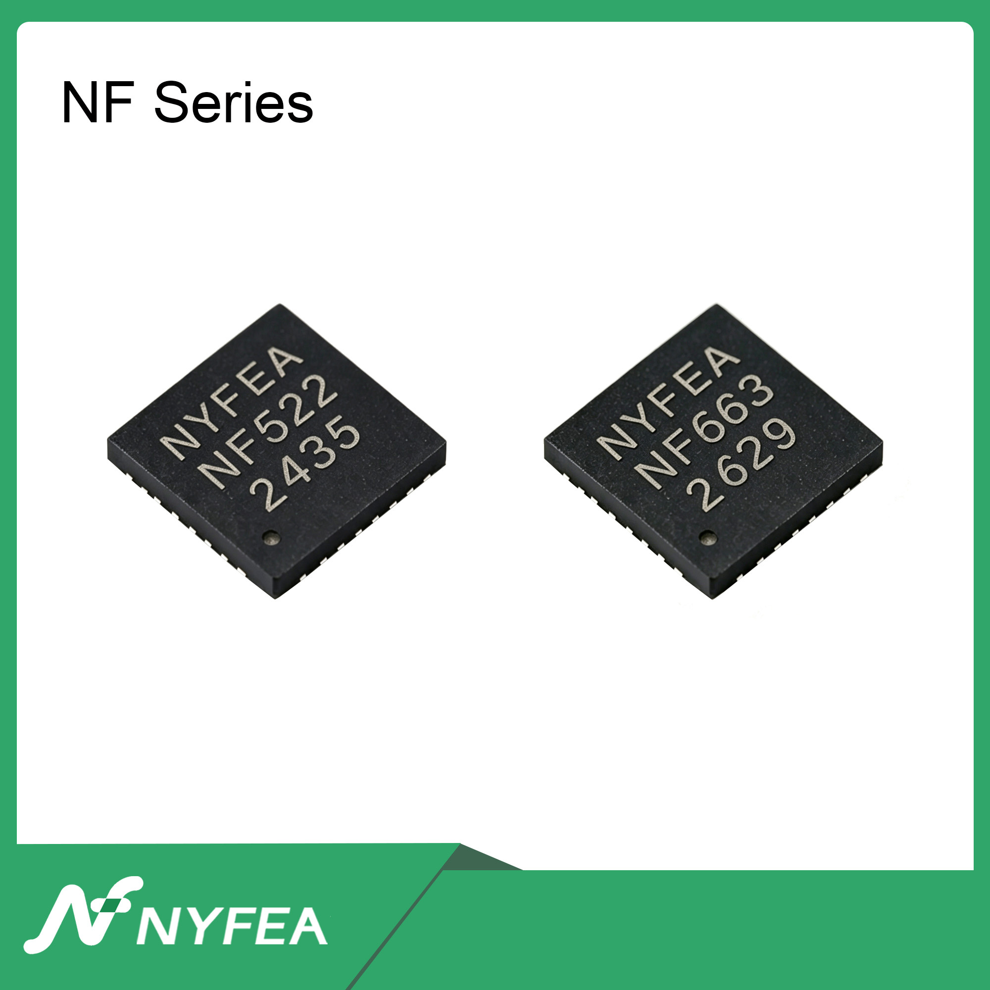
Using This Test Plan to Evaluate NYFEA NF663
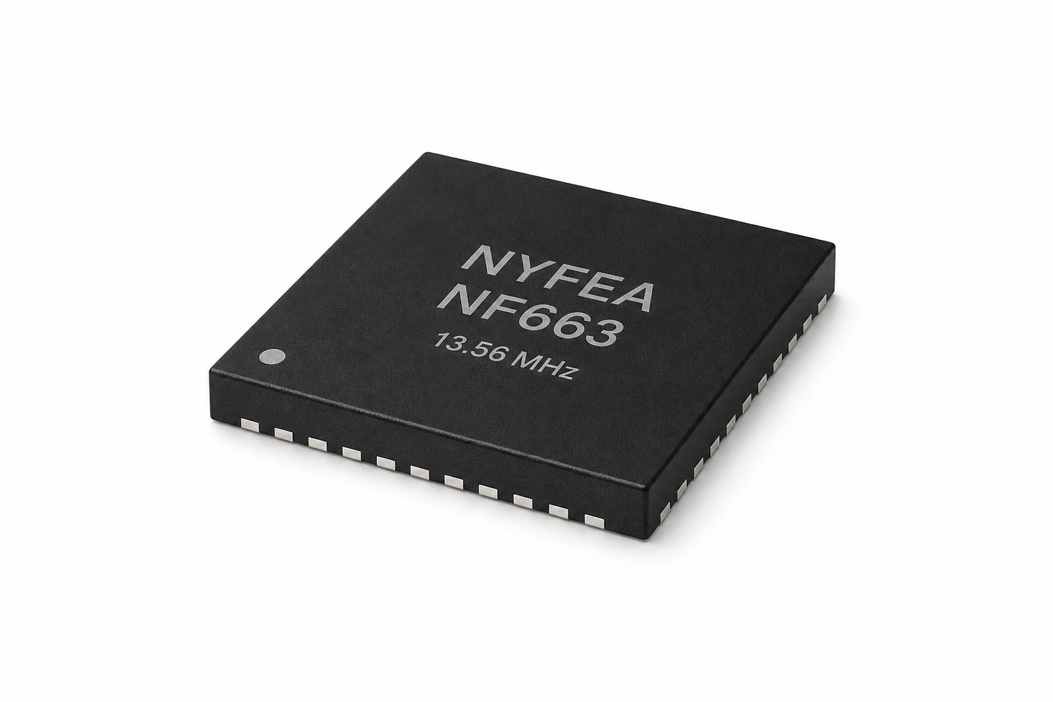
If you are evaluating NYFEA NF663 for an STM32 reader, reuse the protocol checks and log format above as a starting point. NF663 supports ISO/IEC 14443 Type A operation and an SPI host interface; the useful comparison is whether each reader completes the required card-selection tests, not whether a few register names look similar.
Use the NF663 product specification to check interface setup, command behavior and receiver status handling. Keep the application-level test cases, and review or adapt the low-level driver where required.
- Save the CLRC663 baseline, including firmware revision, test conditions and raw protocol records.
- Bring up the NF663 implementation using its documented configuration and an appropriate board and RF network.
- Repeat the same applicable card-selection tests and compare outcomes, timing and recovery behavior. Record hardware differences that prevent a direct comparison.
Conclusion
Start with the first failed exchange and compare what the driver intended with what the reader actually reports. Once single-card selection works, use the same records to validate longer UIDs, collisions and recovery across the intended operating conditions.
Frequently Asked Questions
Why does CLRC663 receive ATQA but not the card UID?
ATQA is a polling response, not a UID. Check the initial 0x93 0x20 request, the transition to full-byte transmission with DataEn preserved, and the receive result before proceeding to SELECT. Repeatable ATQA does not rule out RF-margin problems.
How many bits should CLRC663 transmit for REQA?
REQA is a seven-bit ISO/IEC 14443 Type A short frame. Keep DataEn enabled, set TxLastBits to 7 and disable CRC generation and checking for the REQA/ATQA exchange. For initial CL1, restore TxLastBits to 0 without clearing DataEn.
What response is expected after 0x93 0x20?
With one card and no unresolved collision, initial CL1 returns four cascade-level bytes followed by BCC. A longer UID uses the cascade tag 0x88 in CL1. Validate status, byte count and BCC; exclude cascade tags and BCC from the final UID.
Why does a seven-byte UID require another anticollision level?
A seven-byte UID is split across CL1 and CL2. After a valid CL1 SELECT response, the SAK cascade bit indicates that selection must continue with SEL 0x95. Assemble the UID without the cascade tag or BCC bytes.
Should the antenna be retuned when ATQA is received but UID is missing?
For repeatable ATQA with a fixed card and position, inspect digital framing and command handling first. If those checks pass, investigate RF margin and receiver behavior. Validate the final design across the required card and position range.
Can CLRC663 firmware be copied directly to NF663?
Do not assume direct firmware compatibility. Reuse the protocol-level test plan, check the NF663 specification and adapt the driver where needed. Validate the implementation on NF663 hardware.
Technical References and Case Context
- NXP - CLRC663 and CLRC663 plus Product Data Sheet, Rev. 5.4
- NXP AN12657 - Using the RC663 without library, Rev. 1.0
- NXP Community - Select ISO1443A operation with CLRC663 (reported symptoms, not a verified fix)
- NYFEA - NF663 Product Specification
ISO/IEC 14443A protocol summaries are provided for engineering orientation. Implementations intended for certification or regulated applications must use the applicable licensed standard and project requirements.
NEXT ENGINEERING STEP
Discuss Your NF663 Reader Design
Evaluating NF663 for a new reader? Share your STM32 interface, target card types and current REQA/anticollision logs with NYFEA to discuss the relevant documentation and next evaluation steps.