SHT30 Replacement Passes the Bench but Fails in Production: Why 0x44 Is Not Proof of Compatibility
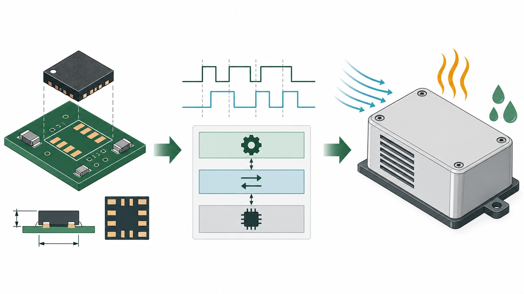
An I²C scanner reports a device at the 7-bit address 0x44. One bench board returns plausible temperature and humidity values. Production units then show timeouts, short reads, CRC faults, driver setup failures, or an offset that appears only after the enclosure is fitted. The results are not contradictory: the scan tested only the first layer of the system.
Direct answer
An ACK at the 7-bit I²C address 0x44 is not proof of compatibility. It establishes only that a device acknowledged that address during one bus operation.
It does not establish that the device accepts every command used by the firmware, returns a complete and CRC-valid measurement frame, behaves within the product error budget, or remains stable after reflow and enclosure assembly.
FROM SHT30 FAILURE TO FHT30 EVALUATION
Why FHT30 is part of this SHT30 discussion
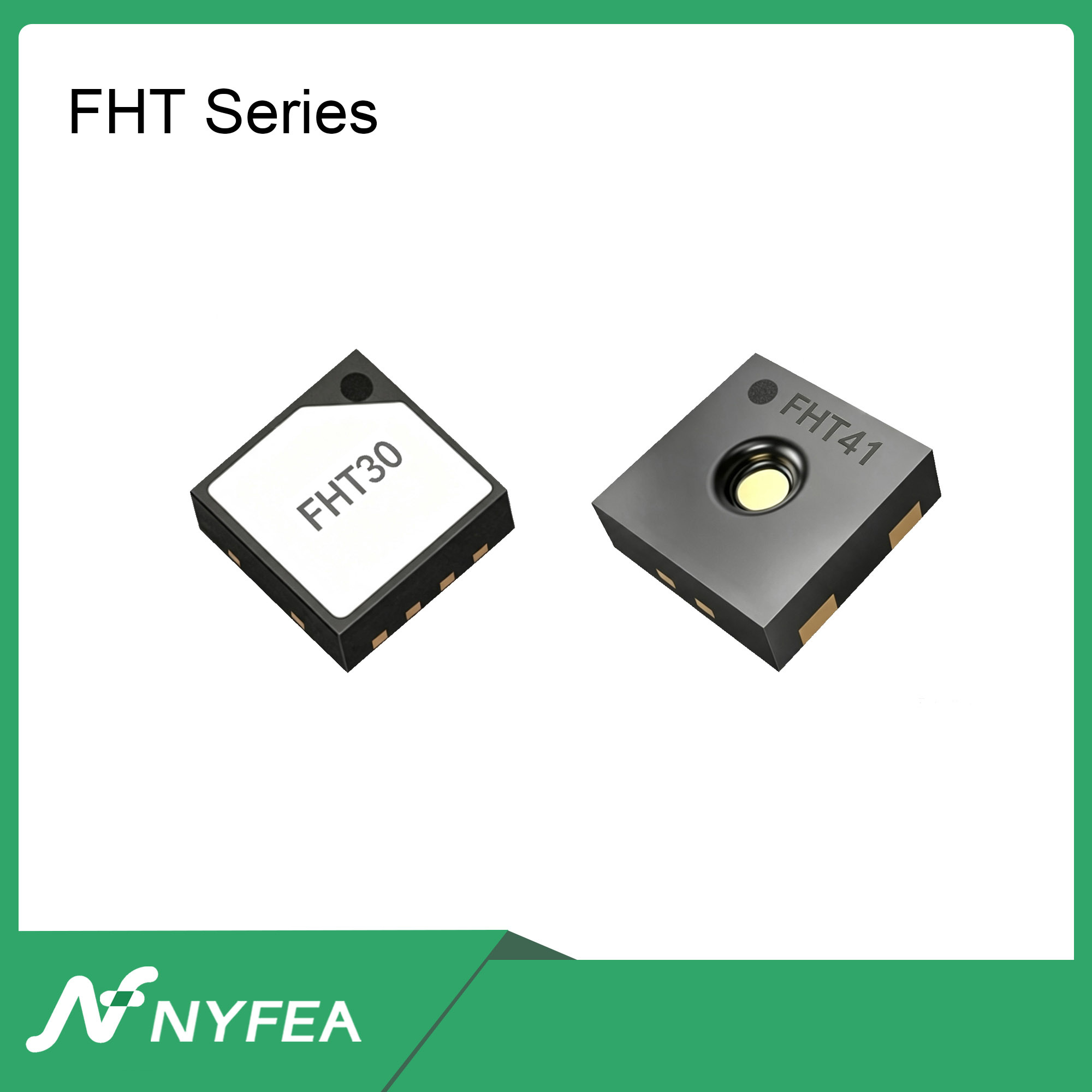
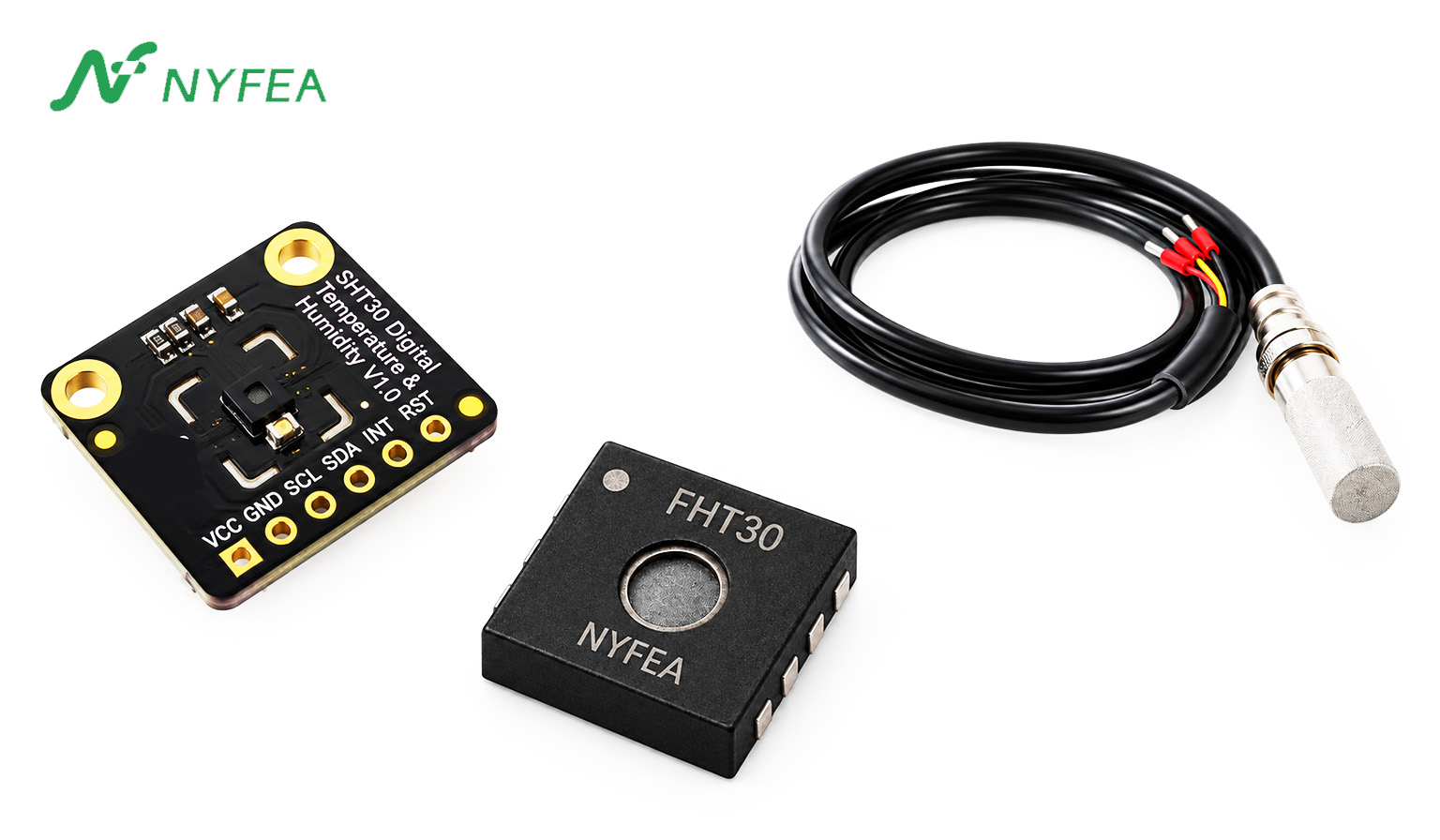
FHT30 is a digital temperature and humidity sensor candidate for engineers reviewing SHT30-class designs. Its documented address options, measurement paths, and CRC-protected temperature/RH data provide a practical starting point for comparison. They do not, by themselves, establish drop-in compatibility.
- What aligns on paper
- Documented
0x44/0x45addressing and familiar measurement-data conventions allow a controlled technical review to begin. - What can be reused
- The existing SHT30 board, deployed firmware, logic captures, and acceptance limits become the reference against which FHT30 samples are tested.
- What still needs proof
- Every command path, timing limit, measurement error, PCB condition, enclosure effect, and production process must be verified on the target product.
First discipline: define the baseline
Before replacing anything, capture the exact original order code, datasheet revision, firmware version, I²C frequency, pull-up values, supply ramp, command list, timeout policy, enclosure state, and acceptable error limits. A generic label such as “SHT30” is not enough to make a controlled comparison.
What an address scan actually tests
An address scan generally sends a START condition, the 7-bit address plus the write bit, and then checks for an ACK. That test can reveal an unpowered device, incorrect wiring, a shorted SDA or SCL line, or an address-selection error. It does not exercise a measurement command, conversion delay, repeated START, six-byte read, CRC validation, reset path, serial-number command, heater control, timeout policy, or the thermal environment inside the finished product.
That distinction matters because real drivers do more than scan. For example, the current ESPHome SHT3xD component attempts identification during setup, sends a measurement command during update, waits before reading, and validates the returned CRC bytes. A recent field report describes a device visible at 0x44 while serial-number and heater operations failed. The address was real; the required command behavior was not established.
DRIVER SOURCE
What the ESPHome SHT3xD driver requests after discovery
0x3780 / 0x3682- Try the supported serial-number read paths during setup.
0x306D / 0x3066- Enable or disable the heater when that path is called.
0x2400- Start the high-repeatability, no-clock-stretching measurement.
50 ms- Wait, read the returned words, and validate their CRC bytes.
Source: ESPHome SHT3xD driver. Commands are summarized from the source rather than presented as a complete driver listing.
PUBLIC FIELD LOG
The address was found; setup still failed
- DiscoveryDevice found at
0x44 - IdentificationSerial number reported as
0x00000000 - SetupDriver reported “Failed to set heater mode”
Engineering reading: the address ACK survived, but the later command path did not supply the behavior expected by the driver.
Source: ESPHome issue #17865. The sequence is condensed from the public report.
SHT30 failure matrix: interpret the first divergence
| Observed symptom | What the result establishes | Next discriminating test |
|---|---|---|
No ACK at 0x44 | Discovery has not been established. | Measure VDD, SDA, SCL, reset, address selection, and bus ownership at the sensor pins. |
ACK at 0x44; setup command fails | The address path works; command compatibility remains open. | Capture the first setup command, both ACK/NACK bits, and the driver's timeout or retry path. |
| Measurement command ACKs; read is empty or short | Command acceptance alone did not complete the conversion/read sequence. | Verify the selected mode, maximum conversion time, repeated START or STOP behavior, and requested byte count. |
| Six bytes arrive; one or both CRC checks fail | A frame was transferred, but its integrity is not established. | Save the raw bytes and compare bus frequency, pull-ups, rise time, supply noise, cable length, and host byte handling. |
| CRC-valid data shifts after enclosure assembly | The digital path works; the measurement environment changed. | Compare open/closed enclosure response and correlate readings with nearby heat-source power states. |
| Failures rise after reflow, cleaning, or humidity exposure | The fault follows production or environmental history. | Separate samples by lot and process step; inspect contamination controls and recovery behavior. |
Trace the real transaction, not just the address
For a common no-clock-stretching single-shot measurement, the host writes a two-byte command such as 0x2400, waits for the selected conversion time, then performs a separate read. The read is only complete when the host receives temperature MSB/LSB/CRC and RH MSB/LSB/CRC, then terminates the exchange correctly. The exact command and maximum conversion time must be taken from the controlled datasheet for the mode in use.
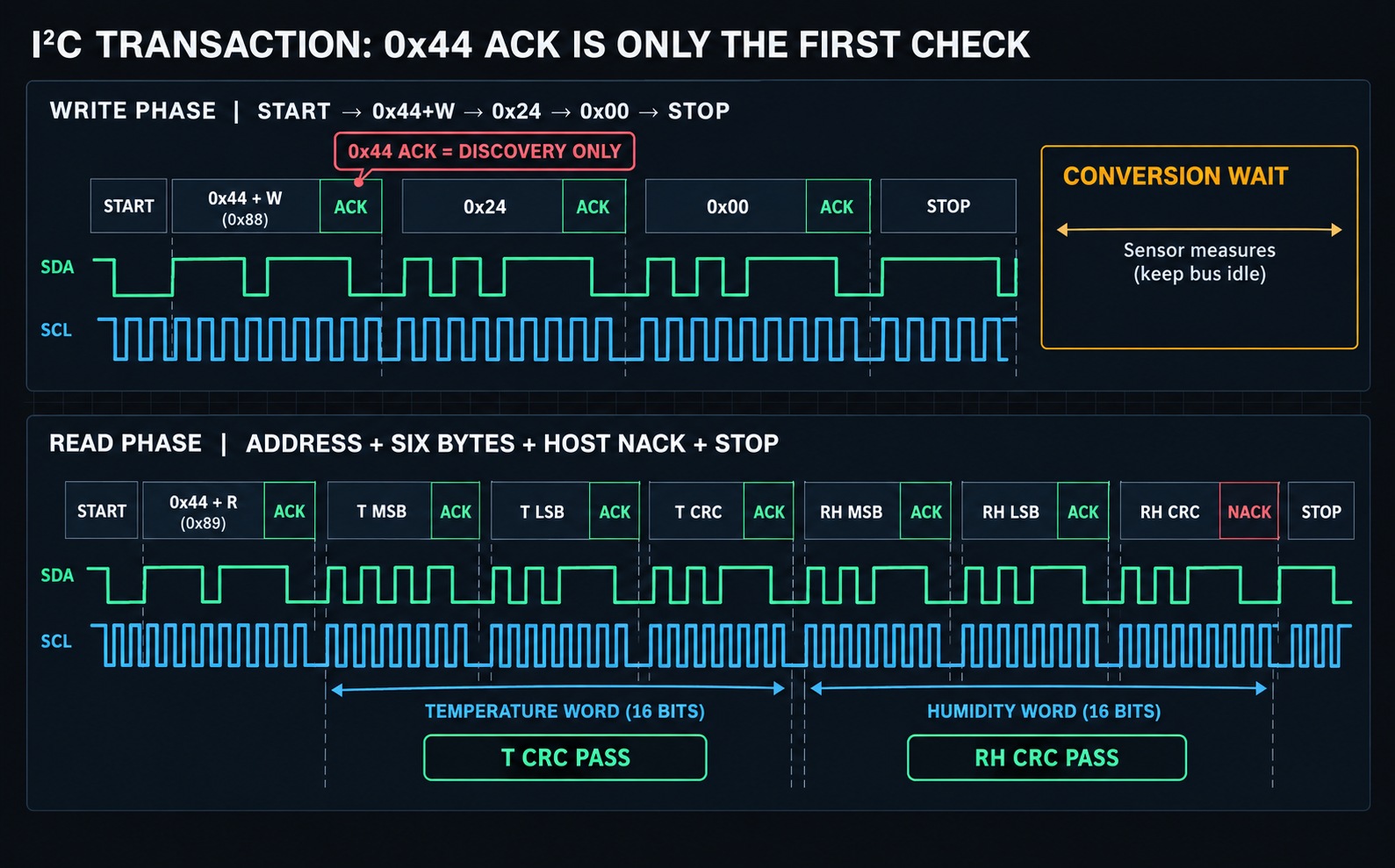
0x2400 single-shot path. The address ACK establishes discovery only; qualification continues through the command, wait, exact six-byte frame, both CRC results, and clean termination. This is not presented as measured waveform data.Use a failure trace as a question, not as a blame assignment
Capture SDA, SCL, supply, and reset when the first failure occurs. Then ask where the sequence diverges. A NACK on the address points toward discovery or bus ownership. A NACK after a command points toward the command set, framing, device state, or timing. A valid command ACK followed by an early read can create an apparent “no data” failure even when the device is fine. A complete frame with a bad CRC points toward integrity, bus waveform, timing, or a byte-handling defect.
Change one variable at a time. Swap only the sensor, then only the firmware, then only the bus speed or pull-up network. “It worked at 100 kHz” is evidence about one operating point, not an explanation. The aim is to make the fault move or disappear under a discriminating change.
Do not turn CRC off to make the error disappear
The common SHT3x-style result contains six bytes: two temperature bytes, their CRC, two humidity bytes, and their CRC. The two words need separate CRC checks. For the published SHT3x-DIS protocol, the CRC-8 parameters are polynomial 0x31, initialization 0xFF, no reflected input/output, and final XOR 0x00. Confirm the protocol for the exact candidate device rather than inheriting assumptions from a library.
When CRC begins failing, log the raw six bytes, the selected command, actual wait time, bus frequency, supply voltage, and error count. Do not log only the converted temperature and RH values: conversion erases the byte-level pattern that can distinguish a corrupted frame from a measurement problem.
Useful integrity questions
- Is the frame always exactly six bytes, including both CRC bytes?
- Does the fault follow a bus speed, cable length, pull-up, supply, or temperature change?
- Does only one word fail CRC, or do both fail together?
- Are retries masking a rising production error rate that should instead be counted?
Valid I²C data can still be the wrong ambient measurement
A digital transaction can be electrically perfect while the sensor measures a local microclimate rather than the intended air. The SHTxx design guide specifically warns about nearby heat sources and poor air exchange. A warm MCU, radio, regulator, display, or copper path can raise sensor temperature. Since relative humidity depends on temperature, the same thermal bias can also change reported RH without a single I²C error.
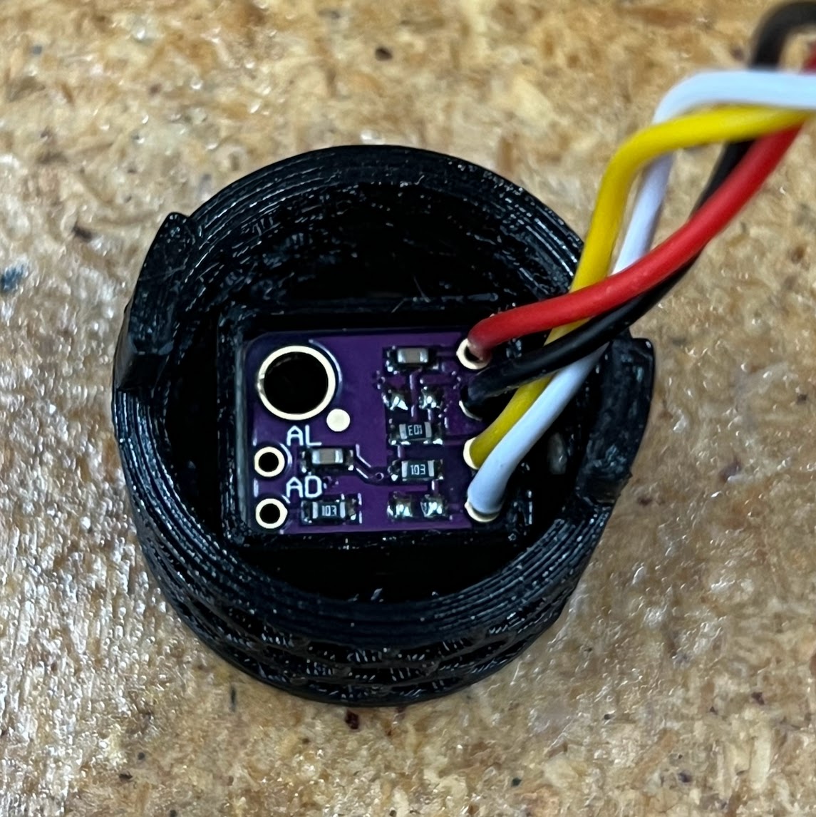
The purple sensor daughterboard is physically separated from the ESP32, power electronics, and high-power LEDs. The bus can work correctly while nearby heat still biases temperature and relative humidity; the wired, ventilated mounting creates a separate thermal zone for the sensing node.
- Failure mechanism: board heat, not an I²C address fault.
- Design response: physical separation plus direct air access.
- Qualification check: compare heat-source states and enclosure-open/closed response.
Enclosure geometry adds another mechanism. A small aperture or a large stagnant volume can slow the humidity step response. The product may look stable in a room test but lag a real humidity event, then be incorrectly “corrected” with a software offset. Contamination, cleaning chemistry, and high-humidity exposure are separate risks that should be evaluated with the finished manufacturing process.
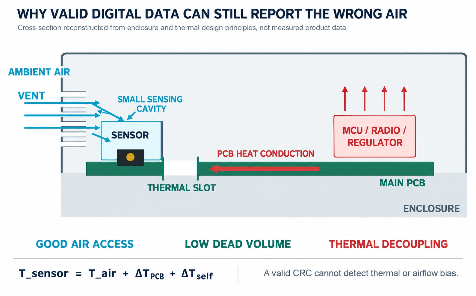
A controlled test before adding an offset
Hold room conditions steady, then switch the nearby heat source between known states. Record sensor temperature, RH, supply, and time. Repeat with the enclosure open and closed. If the reported values track power state or enclosure geometry, the primary problem is physical coupling or air exchange. Fix placement, conduction path, aperture, and dead volume before using firmware compensation.
From SHT30 evidence to an FHT30 evaluation
After the original design has a measured baseline, an alternative can be screened against it. Package fit, address options, a familiar measurement command, and CRC behavior can reduce the cost of beginning an evaluation. They are useful entry conditions, not release conditions.
FHT30 is one candidate that can enter this process. Its public documentation lists the 0x44/0x45 address options and commonly used measurement and CRC conventions, which lowers the effort required to begin a controlled firmware comparison. Before design freeze, record any difference in startup behavior, commands, timing, electrical limits, measurement tolerance, protective configuration, and environmental handling against the exact original order code.
What the documentation lets you test
| Documented evidence | What it permits | What remains unproven |
|---|---|---|
0x44/0x45 address options | Compare ADDR configuration and confirm 7-bit discovery on the target board. | Support for the deployed command set, timing, recovery, and shared-bus conditions. |
| Single-shot measurement paths and CRC-protected temperature/RH words | Build an A/B logic-analyzer test for commands, waits, six-byte frames, and both CRC results. | Correct behavior through every setup, status, heater, reset, timeout, and retry path used by the product. |
| Published package, supply, and measurement limits | Begin footprint, schematic, layout, and error-budget screening against the controlled baseline. | Performance after the actual reflow, cleaning, enclosure assembly, environmental exposure, and production-lot variation. |
Record qualification status precisely
Use three separate states in the engineering record: documented alignment for datasheet similarities, bench verified for tests completed on prototype hardware, and product qualified only after the finished assembly and production process meet their acceptance limits.
FHT30 release gates for an existing SHT30 design
Use these six gates after the document review and bench comparison. Each gate requires retained evidence from the original SHT30 design and the FHT30 candidate. If one gate remains open, record FHT30 as under evaluation, not qualified for production.
- Freeze the SHT30 referenceRetain the exact SHT30 order code, golden-board readings, firmware, schematic, layout, enclosure state, and pass limits. This is the baseline FHT30 must meet.
- Confirm FHT30 discoveryOn the target PCB, verify ADDR selection,
0x44/0x45behavior, logic levels, supply range, pull-ups, rise time, and shared-bus ownership. - Replay the deployed firmwareRun every setup, identification, reset, status, heater, and measurement path used by the SHT30 production firmware. Record the first FHT30 ACK, NACK, timeout, or timing difference.
- Validate FHT30 data integrityRetain raw six-byte frames, both CRC results, error counts, retry behavior, timeout recovery, and logic-analyzer captures at the required bus conditions.
- Compare finished-product measurementsMeasure SHT30 and FHT30 units against the same reference through temperature/RH steps, heat-source state changes, and enclosure-open/closed tests. Apply the product error budget, not typical values alone.
- Release the production processVerify FHT30 results after the actual reflow, cleaning, material exposure, high-humidity recovery, and enclosure assembly across the approved sample and lot plan.
Conclusion
A useful failure report ends with the first layer that lacks evidence. If discovery fails, investigate power, wiring, address selection, and bus ownership. If setup or measurement commands fail, compare the transaction and driver paths. If complete frames fail CRC, preserve the raw bytes and waveform. If valid frames drift only after assembly, investigate heat, airflow, contamination, and process variation.
That structure turns an ambiguous “replacement failed” report into a bounded engineering decision. Use the exact original order code and deployed command sequence as the baseline, then evaluate the FHT30 product information and physical samples against the open evidence.
FAQ
What does a response at I²C address 0x44 actually prove?
It proves that a device acknowledged the 7-bit address during that bus operation. It does not prove command support, conversion timing, frame length, CRC validity, reset behavior, measurement accuracy, or production consistency.
Why can a sensor appear at 0x44 but fail during setup?
The driver may call serial-number, status, heater, or reset commands after the scan. Capture the first command that receives a NACK or times out; that first divergence is more useful than repeating the address scan.
What should an I²C logic-analyzer capture include?
Capture power-up through the first failed measurement. Preserve START and repeated START conditions, address direction, every command byte and ACK/NACK, the conversion wait, all six returned bytes, both CRC results, STOP, supply voltage, and reset timing.
Should I lower the I²C frequency first?
Use it as one controlled test, not as an automatic fix. If 20 kHz, 50 kHz, and 100 kHz fail at the same transaction point, investigate command support, device state, wait timing, pull-ups, and the host driver instead of blaming frequency alone.
Can CRC checking be disabled when the values look reasonable?
No for production qualification. Log the raw frame and separate temperature-word and humidity-word CRC failures; disabling CRC removes the evidence needed to distinguish bus corruption from a genuine measurement change.
Why do readings change after the enclosure is closed?
The sensor may be measuring air warmed by the PCB or trapped in a slow-exchange cavity. Compare enclosure-open and enclosure-closed response, switch nearby heat sources between known states, and use an external reference probe before applying a software offset.
Can an existing Arduino, ESP32, or ESPHome SHT30 driver be reused?
Possibly, but verify the exact paths used by that driver. Check setup and identification commands, heater and status handling, selected measurement mode, conversion delay, CRC implementation, reset behavior, timeouts, and bus recovery on the target controller.
How many samples or production lots are enough?
There is no universal number. Choose coverage from the product risk and error budget, but include multiple devices and more than one manufacturing lot, then retain initial, post-reflow, environmental, recovery, and failure-rate results rather than relying on one passing board.
Is FHT30 a guaranteed drop-in replacement for every SHT30 design?
No universal claim is appropriate. Its documented interface alignment can justify evaluation, while final suitability depends on the exact SHT30 order code, firmware paths, electrical and measurement limits, PCB, enclosure, environment, and production evidence.
Sources and evidence
- ESPHome issue #17865: field report of a device detected at
0x44while SHT3xD commands failed. - ESPHome SHT3xD driver source: setup, measurement, CRC, and heater command behavior.
- NYFEA FHT30 public datasheet.
Disclosure: NYFEA manufactures and supplies FHT30. This article uses third-party product names only to identify the engineering context; it does not assert affiliation, endorsement, or sponsorship by Sensirion.
Evaluate FHT30 against your SHT30 production requirements
For a project-specific review, provide the exact SHT30 order code, supply voltage, I²C frequency and command list, pull-up network, allowable temperature and RH error, operating environment, PCB and enclosure constraints, expected quantity, and identify whether firmware or hardware may change.
Sensirion, SHT30, SHT30-DIS-B, and related names or marks belong to their respective owners. FHT30 is a NYFEA product. NYFEA and FHT30 are not affiliated with, endorsed by, or sponsored by Sensirion. Third-party names identify engineering context only.