ENGINEERING TROUBLESHOOTING GUIDE
SHT40 Temperature Too High and Humidity Too Low?
An SHT40 can return complete, CRC-valid I2C data while reporting temperature above and relative humidity below the intended ambient conditions. This guide separates PCB heating, enclosure bias and slow air exchange with a controlled four-state experiment.
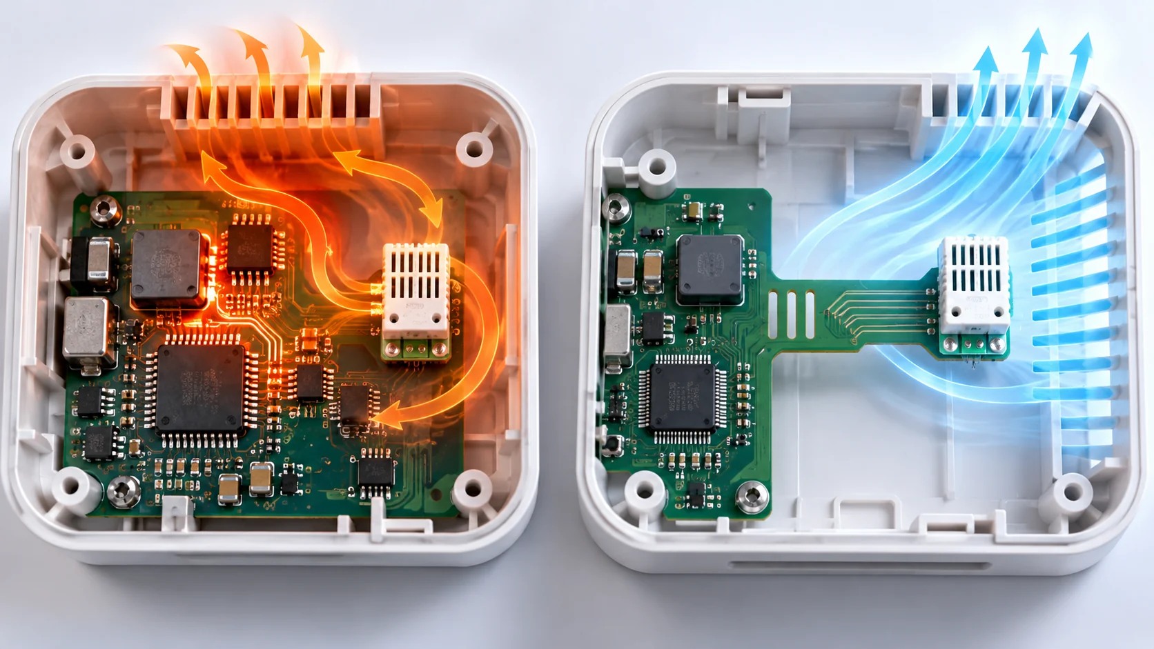
Why can SHT40 temperature read high while humidity reads low?
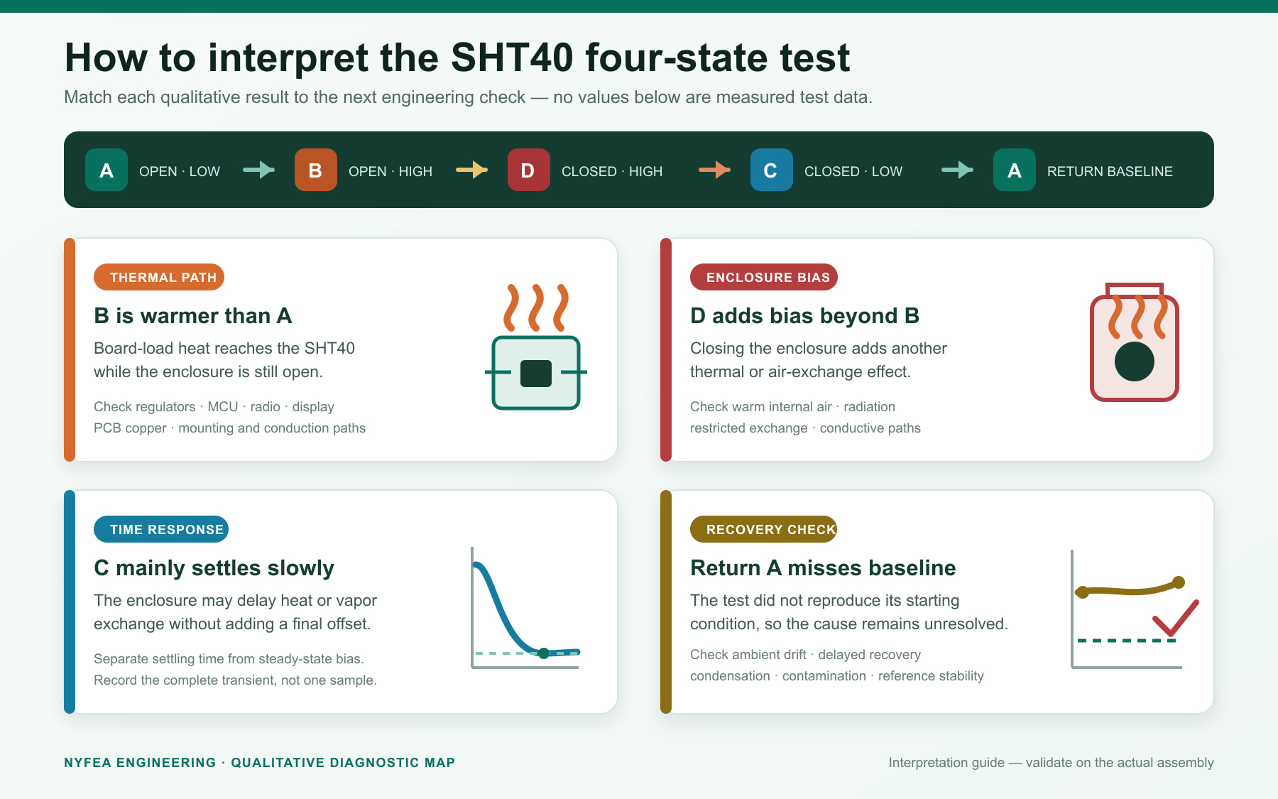
An SHT40 measures the microclimate at its sensing opening, not automatically the room or duct air that the product intends to report. Heat conducted through PCB copper, warm internal air and poor air exchange can raise the local temperature. At approximately constant water-vapor content, that warming also lowers relative humidity. Validate the digital measurement first, then use an A → B → D → C → A test to separate board-load and enclosure effects before applying any correction.
What air is the SHT40 actually measuring?
The SHT40 measures conditions at its local sensing opening. That microclimate may differ from the target environment, such as room air, a duct stream or a sealed chamber. A nearby reference instrument can therefore report a different value even when both instruments operate correctly.
Define the measurement target before assigning an accuracy error. Record the reference-probe position, height, orientation and distance from the SHT40. Keep both sensors away from direct sunlight, people, HVAC discharge air and temporary heat sources unless those are part of the intended test.
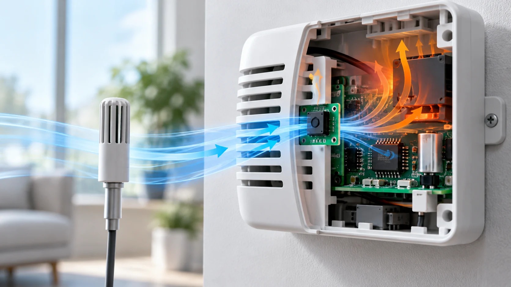
Why does local warming reduce relative humidity?
Relative humidity is temperature dependent. At approximately constant water-vapor content, warming increases the saturation vapor pressure and lowers the reported relative humidity. One local thermal problem can therefore appear as two faults: temperature too high and humidity too low.
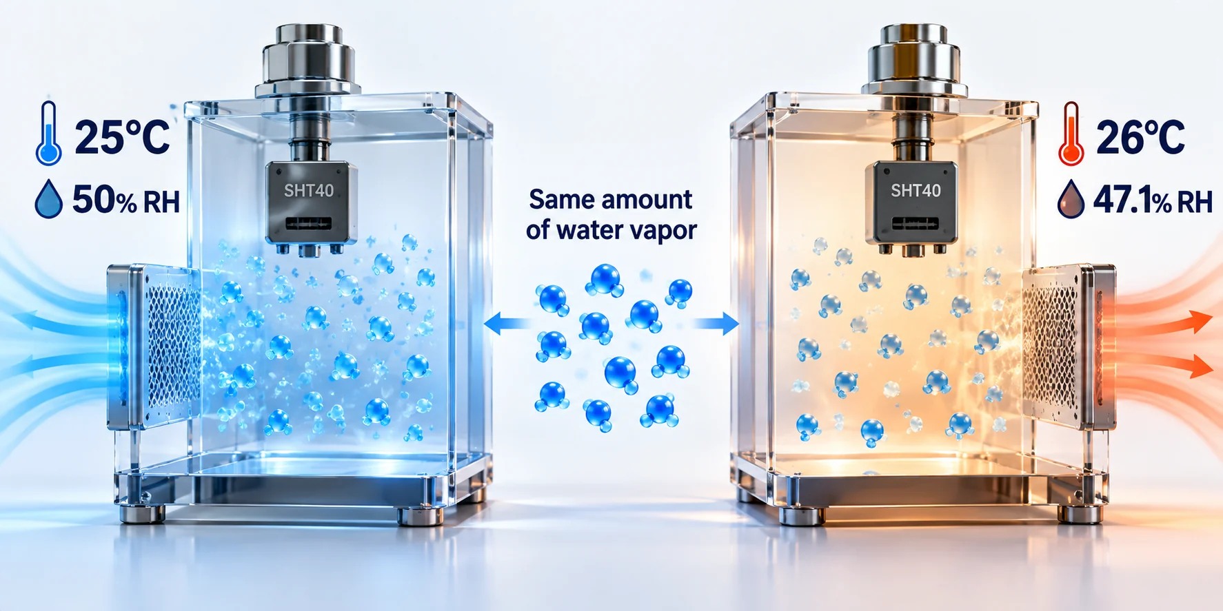
Use this constant-water-vapor approximation as a diagnostic comparison. If measured RH is close to the predicted value, local warming may explain much of the difference, but the calculation does not identify the heat source. A significant residual requires checks for air exchange, moisture exchange, sensor condition, reference uncertainty and data processing.
Verify the SHT40 circuit and digital data first
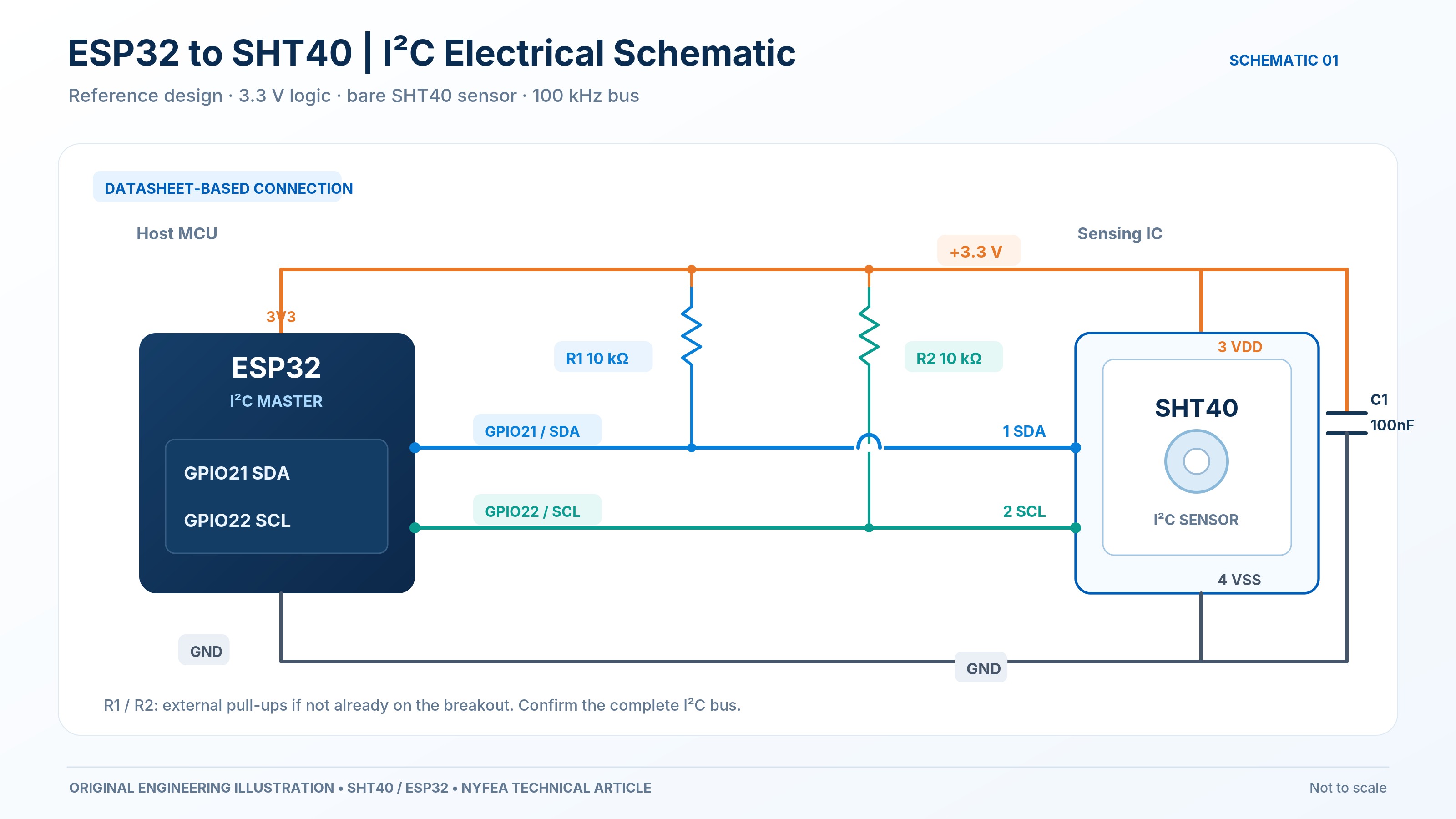
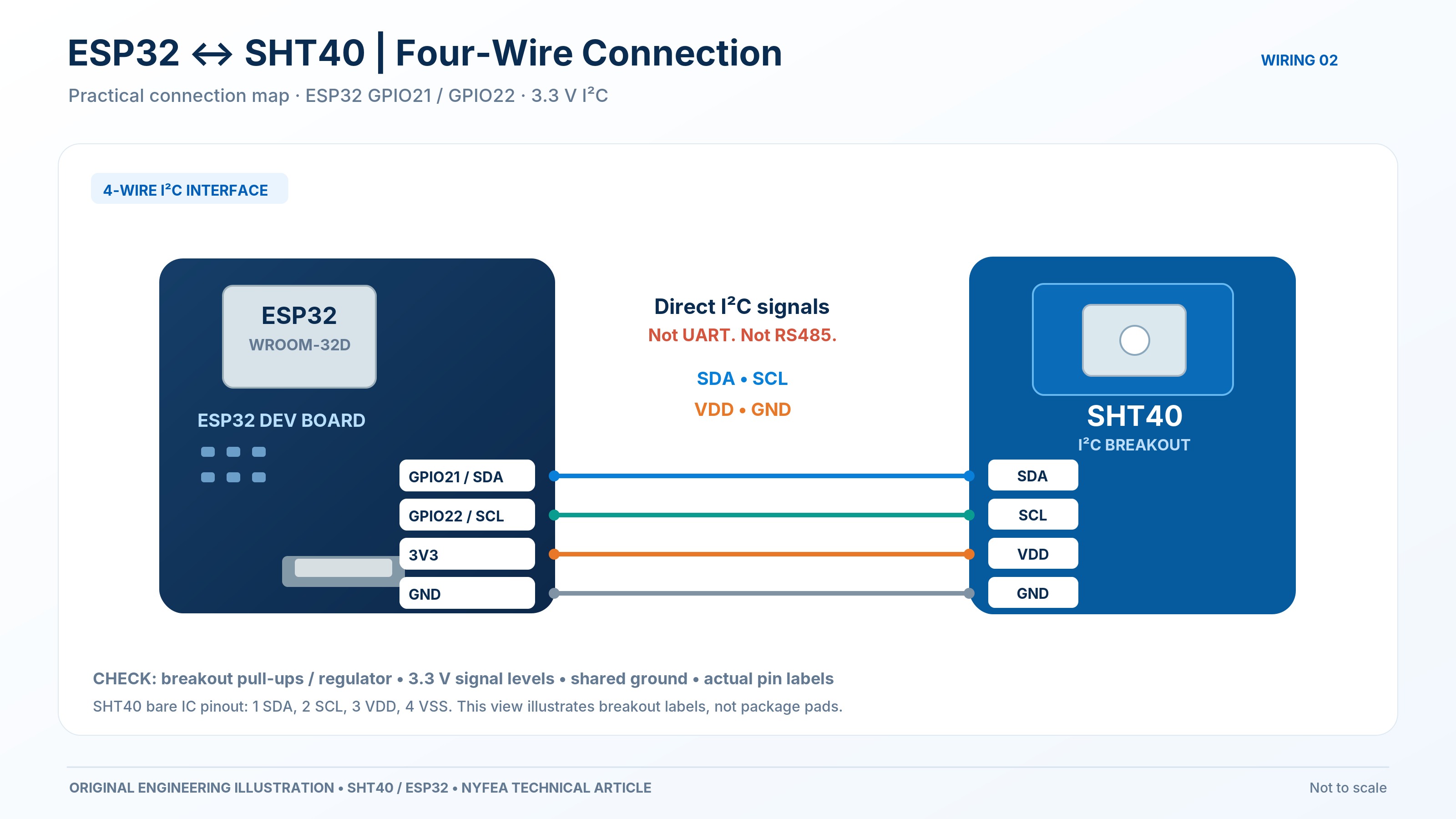
Do not use a thermal explanation for a bus fault. Confirm the exact SHT40 order code, supply voltage, I2C address and wiring. The example below uses address 0x44, a 3.3 V ESP32 bus, 10 kΩ example pull-ups and a 100 nF bypass capacitor. Final pull-up values must satisfy the actual bus capacitance, rise time, logic levels and any resistors already present on a breakout.
| Check | Expected evidence | What it does not prove |
|---|---|---|
| Address | ACK at the configured 7-bit address | Command support, complete data or measurement accuracy |
| Command | 0xFD accepted for high-repeatability measurement | That conversion has completed |
| Timing | Wait at least the documented maximum conversion time; this logger uses 10 ms | Product-level thermal stabilization |
| Read | Exactly six bytes: temperature word + CRC, RH word + CRC | That the sensor sees the intended air |
| Integrity | CRC-8 passes separately for both 16-bit words | System accuracy or enclosure suitability |
Electrical safety check
The bare SHT40 supply range and a breakout board's input-voltage rating are not interchangeable. Confirm whether a module includes regulation or level shifting, and never infer a safe voltage from a similar-looking carrier board.
Use four states to isolate board and enclosure effects
Keep the same SHT40 command, sample interval and reference arrangement throughout the experiment. Do not activate the internal heater. Change only one condition at each transition: enclosure state or board load.
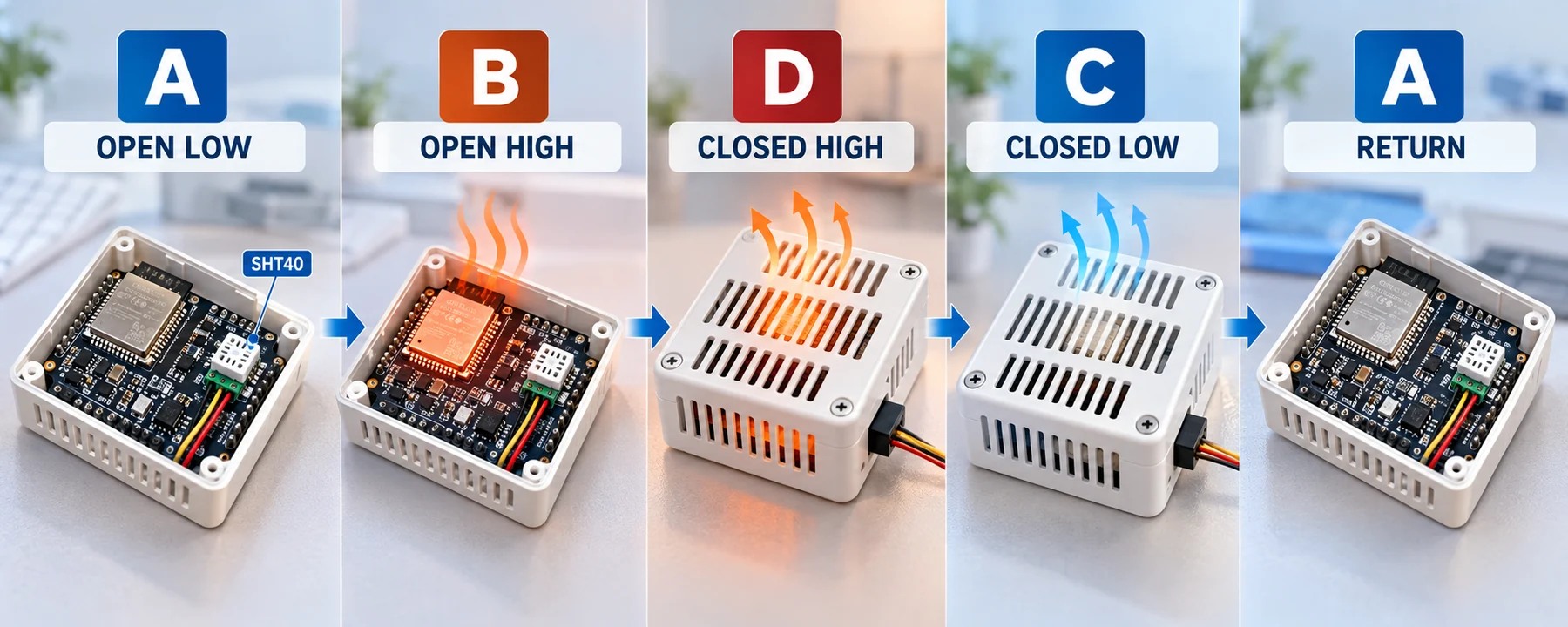
| State | Enclosure | Board load | Question |
|---|---|---|---|
| A | Open | Low | What is the baseline offset? |
| B | Open | High | Does board load affect the sensor without a closed enclosure? |
| D | Closed | High | What additional effect appears after enclosure closure? |
| C | Closed | Low | Does the enclosure retain heat or mainly slow the response? |
| Return A | Open | Low | Does the original baseline recover? |
Log state, elapsed time, SHT40 temperature and RH, digital-validity status, reference temperature and reference RH. Compare both steady offsets and time to settle. A slower response is not automatically a permanent measurement offset.
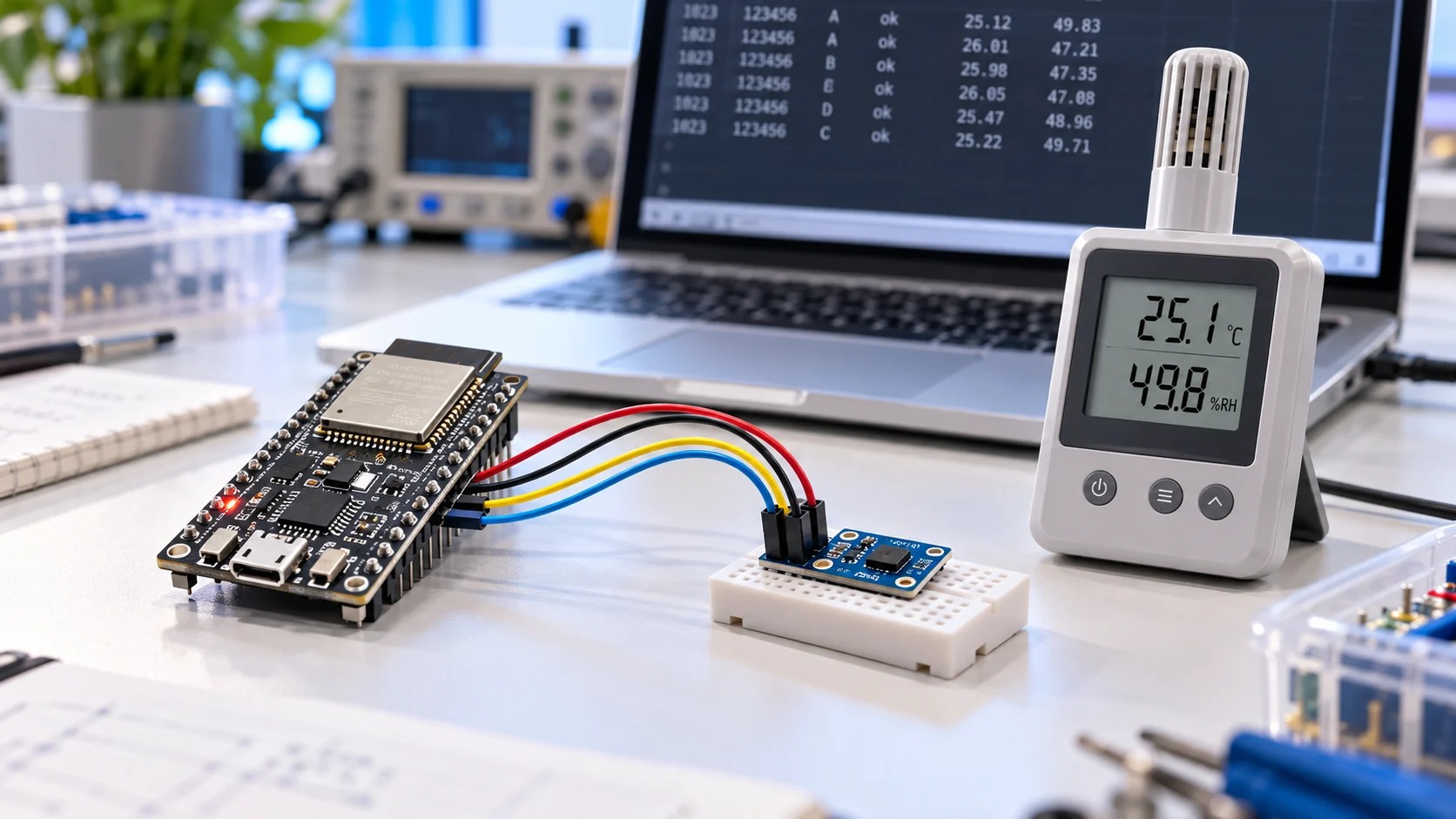
ESP32 Arduino logger for the four-state test
The logger uses direct I2C transactions so that the command, requested byte count and two CRC results remain visible. It records raw words and reports short reads, write failures and separate CRC failures instead of silently converting invalid data.
#include <Arduino.h>
#include <Wire.h>

// Verify the I2C address of your exact SHT40 variant.
constexpr uint8_t SHT40_ADDRESS = 0x44;
constexpr int SDA_PIN = 21;
constexpr int SCL_PIN = 22;

char phase = 'U';  // U: test state has not been marked
uint32_t sampleNo = 0;

enum class Status {
  Ok,
  NoAck,
  WriteFailed,
  ShortRead,
  TemperatureCrcFailed,
  HumidityCrcFailed
};

struct Reading {
  uint16_t rawTemperature;
  uint16_t rawHumidity;
  float temperatureC;
  float humidityRH;
};

const char* statusText(Status status) {
  switch (status) {
    case Status::Ok:                   return "ok";
    case Status::NoAck:                return "no_ack";
    case Status::WriteFailed:          return "write_failed";
    case Status::ShortRead:            return "short_read";
    case Status::TemperatureCrcFailed: return "temperature_crc_failed";
    case Status::HumidityCrcFailed:    return "humidity_crc_failed";
  }
  return "unknown";
}

uint8_t crc8TwoBytes(const uint8_t* data) {
  uint8_t crc = 0xFF;
  for (uint8_t i = 0; i < 2; ++i) {
    crc ^= data[i];
    for (uint8_t bit = 0; bit < 8; ++bit) {
      crc = (crc & 0x80)
          ? uint8_t((crc << 1) ^ 0x31)
          : uint8_t(crc << 1);
    }
  }
  return crc;
}

Status readSHT40(Reading& reading) {
  Wire.beginTransmission(SHT40_ADDRESS);
  Wire.write(uint8_t(0xFD));

  const uint8_t writeResult = Wire.endTransmission();
  if (writeResult == 2) return Status::NoAck;
  if (writeResult != 0) return Status::WriteFailed;

  // 0xFD high-repeatability conversion: max. 8.3 ms.
  delay(10);

  const uint8_t count = Wire.requestFrom(SHT40_ADDRESS, uint8_t(6));
  if (count != 6) {
    while (Wire.available()) Wire.read();
    return Status::ShortRead;
  }

  uint8_t data[6];
  for (uint8_t i = 0; i < 6; ++i) {
    data[i] = uint8_t(Wire.read());
  }

  if (crc8TwoBytes(&data[0]) != data[2])
    return Status::TemperatureCrcFailed;
  if (crc8TwoBytes(&data[3]) != data[5])
    return Status::HumidityCrcFailed;

  reading.rawTemperature =
      (uint16_t(data[0]) << 8) | data[1];
  reading.rawHumidity =
      (uint16_t(data[3]) << 8) | data[4];

  reading.temperatureC =
      -45.0f + 175.0f * reading.rawTemperature / 65535.0f;
  reading.humidityRH =
      -6.0f + 125.0f * reading.rawHumidity / 65535.0f;

  return Status::Ok;
}

void readPhaseCommand() {
  while (Serial.available()) {
    const char command = char(Serial.read());
    if (command >= 'A' && command <= 'D') {
      phase = command;
    }
  }
}

void setup() {
  Serial.begin(115200);
  Wire.begin(SDA_PIN, SCL_PIN, 100000);
  Serial.println(
      "sample,ms,phase,status,temperature_c,humidity_rh,raw_t,raw_rh");
}

void loop() {
  readPhaseCommand();

  Reading reading = {};
  const Status status = readSHT40(reading);

  Serial.print(++sampleNo);
  Serial.print(',');
  Serial.print(millis());
  Serial.print(',');
  Serial.print(phase);
  Serial.print(',');
  Serial.print(statusText(status));

  if (status == Status::Ok) {
    Serial.print(',');
    Serial.print(reading.temperatureC, 2);
    Serial.print(',');
    Serial.print(reading.humidityRH, 2);
    Serial.print(',');
    Serial.print(reading.rawTemperature);
    Serial.print(',');
    Serial.print(reading.rawHumidity);
    Serial.println();
  } else {
    Serial.println(",,,,");
  }

  delay(1000);
}
The ms field is elapsed time since boot, not a wall-clock timestamp. The phase field is a manual annotation; the code does not switch the board load or enclosure. RH is deliberately left uncropped so that nonphysical values remain visible during diagnosis.
How to interpret the four-state results
B is warmer than A
Board load reaches the sensor with the enclosure open. Inspect regulators, processors, radios, displays, copper areas and mechanical conduction paths.
D adds bias beyond B
The closed enclosure amplifies the high-load effect. Investigate warm internal air, radiation, limited exchange and conductive paths.

C mainly settles slowly
The enclosure may be delaying air or vapor exchange rather than creating a permanent steady offset. Separate time response from final bias.

Return A misses baseline
Check ambient drift, delayed recovery, condensation, contamination and reference-instrument stability before accepting a root-cause conclusion.
If temperature-based RH prediction explains most of the humidity difference, prioritize thermal isolation and placement. If a large residual remains, investigate whether the two instruments sampled different air, whether moisture exchange was restricted, and whether the reference uncertainty is small enough to support the conclusion.
Improve SHT40 PCB layout and enclosure airflow
Thermal mitigation should follow a repeatable diagnosis. Useful options can include greater distance from hot electronics, narrower conductive paths into the sensing area, an isolated sensor peninsula, a separate sensing cavity and a shorter path between ambient air and the sensing opening.
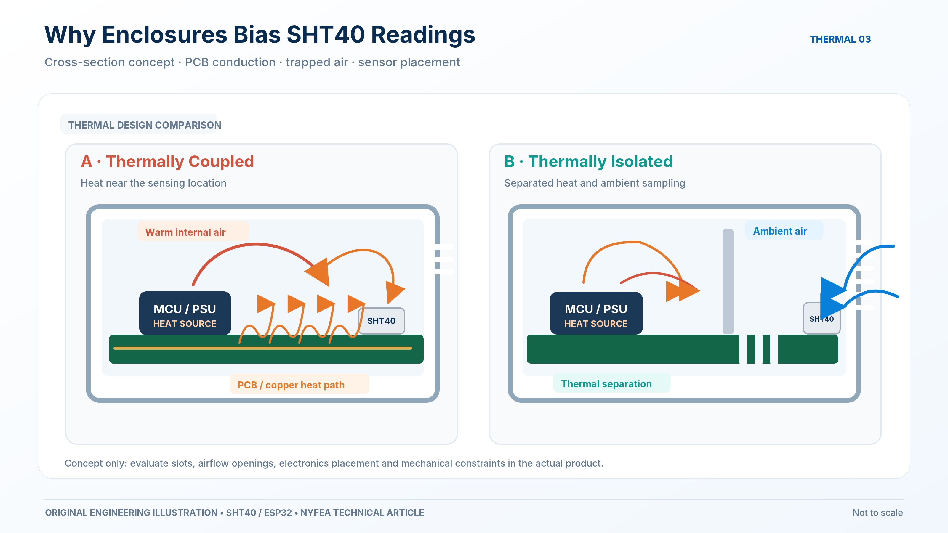
- Keep regulators, MCUs, radios and displays away from the sensing element where practical.
- Avoid unnecessary copper or thermal mass below and around the sensor.
- Place the sensing opening where it samples the target air rather than a trapped local volume.
- Improve air exchange without exposing the device to water, chemicals, direct heat or contamination.
- Repeat the four-state experiment after each material PCB or enclosure change.
These are design options, not guaranteed fixes. Validate mechanical, electrical, environmental, manufacturing and reliability requirements in the finished product.
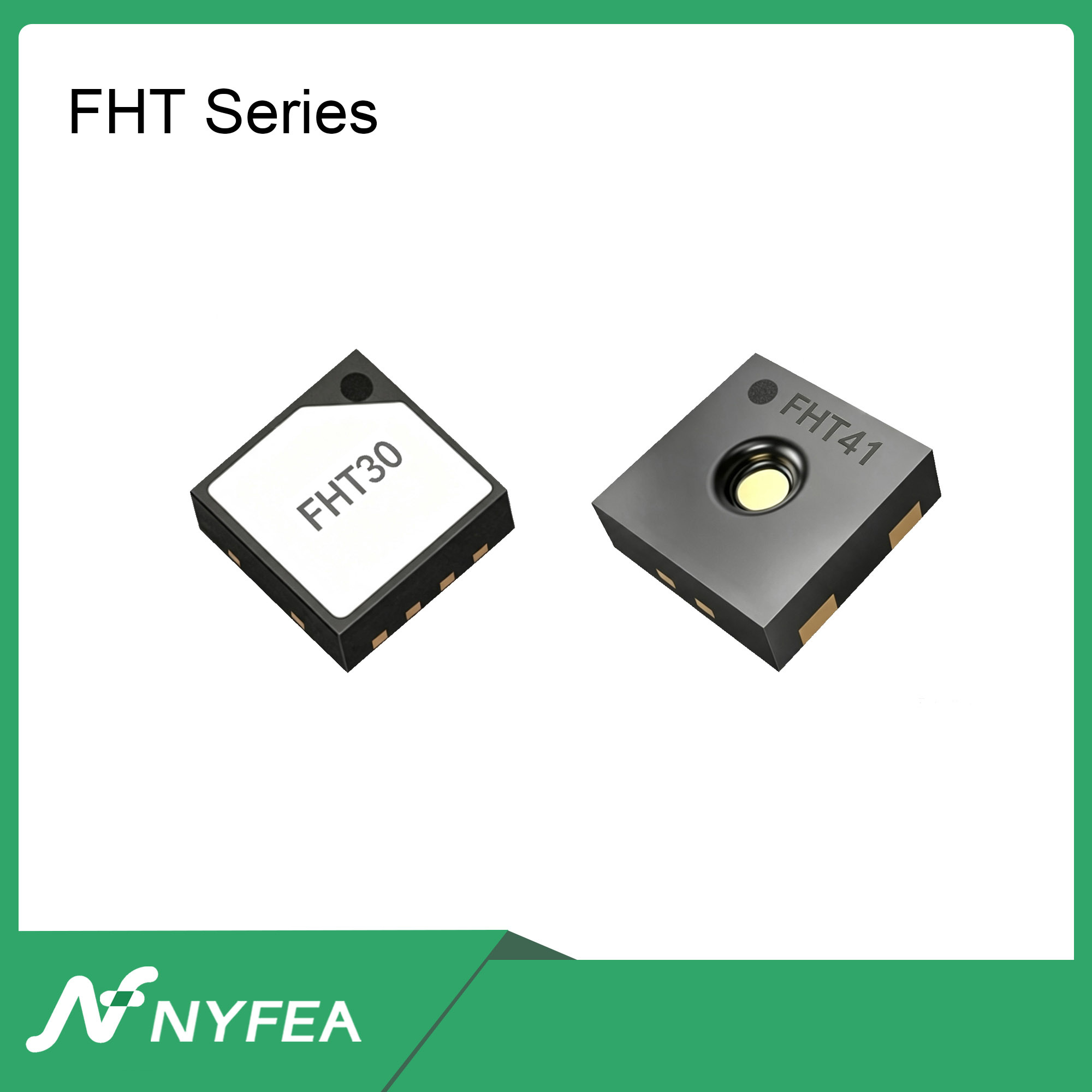
When should engineers evaluate NYFEA FHT40?
NYFEA FHT40 is a candidate for evaluation in SHT40-based designs, not a validated drop-in replacement. Compare the exact controlled specifications, supply range, package and footprint, address and commands, timing, accuracy limits, heater behavior, environmental restrictions and production process.
Use the same reference instrument, target air, enclosure, board-load sequence and acceptance limits for both devices. Replacing a sensor does not remove PCB heat conduction, trapped air or an unrepresentative sensing location.
| Evidence layer | Required check | Release meaning |
|---|---|---|
| Documents | Compare controlled electrical, protocol, mechanical and environmental limits | Candidate can enter evaluation |
| Bench | Run complete command, timing, CRC and fault-handling paths | Prototype behavior is characterized |
| Assembly | Repeat accuracy, transient, enclosure and process testing | Finished-product suitability can be judged |
| Production | Apply sample, lot, reflow, cleaning and environmental acceptance plans | Production qualification may be released |
Common SHT40 troubleshooting questions
Why does my SHT40 show a higher temperature and lower humidity?
Local heating is one plausible cause. Air warmed near the sensor can raise measured temperature and lower relative humidity even when the amount of water vapor is nearly unchanged. Compare the SHT40 with an independent reference and run the four-state test before assigning a calibration error.
Can PCB self-heating affect SHT40 humidity readings?
Yes. Heat from a regulator, MCU, display, radio or other component can reach the sensing area through PCB copper or internal air. The magnitude must be measured under controlled low-load and high-load states.
Does a successful I2C transaction prove SHT40 accuracy?
No. A complete six-byte response with valid CRC values establishes digital data integrity for that transaction. It does not prove that the sensor is exposed to the intended target air or that the assembled product meets its accuracy budget.
How can I separate PCB heating from enclosure effects?
Use the A to B to D to C to A sequence. Increase board load while the enclosure is open, close the enclosure without changing load, reduce load while closed, and then return to the open low-load baseline.
Should I apply a fixed humidity offset?
Not before identifying the cause. The relative-humidity effect of warming changes with temperature and humidity, so a universal fixed offset can hide PCB or enclosure problems and fail at other operating points.
How long should I wait for the SHT40 reading to stabilize?
There is no universal full-product stabilization time. Record the complete transient, define a repeatable stability criterion, and evaluate steady offsets separately from response-time changes.
A trustworthy humidity reading depends on the whole design
High SHT40 temperature and low RH do not automatically prove that the sensor is defective. Define the target air, validate the digital data, measure controlled board and enclosure states, and compare both steady offsets and transient response. Use the temperature-based RH estimate as a diagnostic aid rather than as a substitute for calibration or uncertainty analysis.
Technical sources
- Sensirion — Design Guide for Humidity and Temperature Sensors, Version 2, March 2024. Relative-humidity temperature relationship, heat-source separation, PCB coupling and airflow guidance.
- Sensirion — Datasheet SHT4x, Version 7.3, June 2026. Pin assignment, I2C commands, conversion timing, data format, CRC and output formulas.
- NYFEA — FHT40 product page. Candidate product information; confirm the current controlled specification before design release.
Evaluate the sensor in the finished assembly
Provide the exact sensor order code, supply voltage, I2C command list, PCB layout, enclosure drawings, target accuracy and operating environment for a controlled technical review.
Review NYFEA FHT40Request samples or an engineering review