Looking for an SHT41 Alternative? How to Evaluate NYFEA FHT41
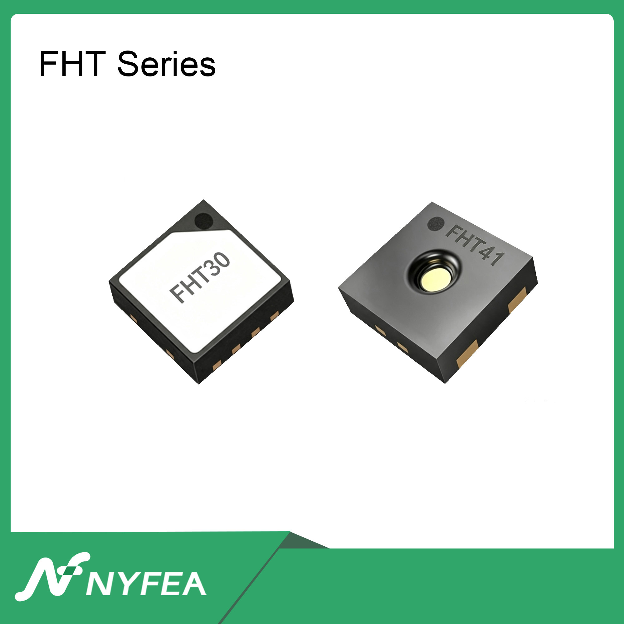
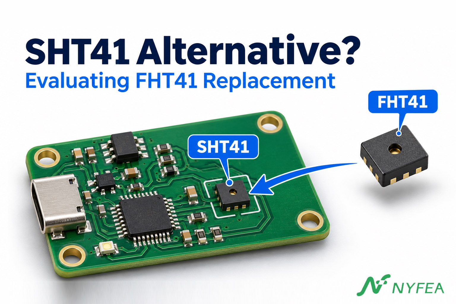
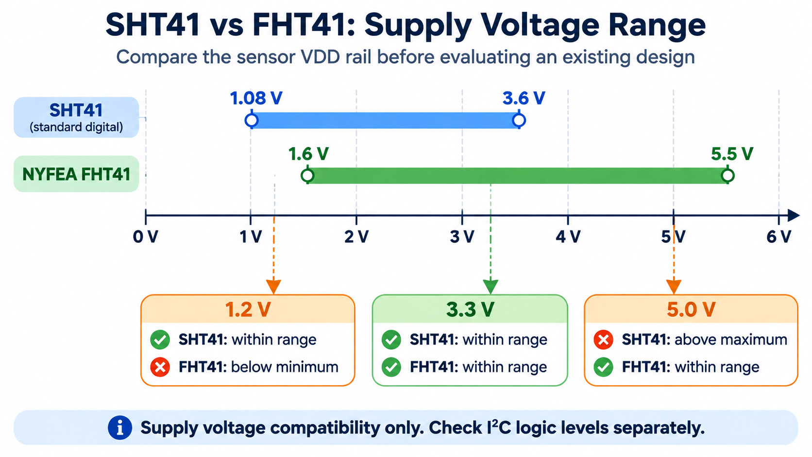
NYFEA FHT41 is a candidate for evaluating an SHT41 replacement. Its 1.6–5.5 V operating supply makes a 3.3 V design a starting point for review; a 1.2 V sensor rail requires a supply change. Confirm the supplied part’s I²C address, electrical levels, footprint and driver, then validate the assembled device. NYFEA FHT41 specifications
Is FHT41 a drop-in replacement for SHT41?
FHT41 is an evaluation candidate; this guide does not establish drop-in compatibility with SHT41. The comparison below identifies published similarities, differences and open checks. It presents specifications and a qualification procedure, rather than measured replacement-validation results.
SHT41 vs FHT41: what matters for replacement?
| Check | Sensirion SHT41 | NYFEA FHT41-TR | Design implication |
|---|---|---|---|
| Operating supply | 1.08–3.6 V | 1.6–5.5 V | A 1.2 V sensor rail requires redesign for FHT41; check I²C levels separately. |
| 7-bit I²C address | 0x44 for SHT41-AD1B-R3 and SHT41-AD1F-R2 | Confirmation required: product page lists 0x44; the available FHT41-TR PDF ordering table lists 0x45. | Obtain the address for the supplied order code before configuring the driver. |
| Typical humidity accuracy | ±1.8 %RH; consult the SHT41 accuracy curves | ±1.8 %RH; consult the FHT41 accuracy curves | Compare conditions and maximum limits across the required range; typical figures are not finished-device guarantees. |
| Pin assignment | 1: SDA; 2: SCL; 3: VDD; 4: VSS | 1: SDA; 2: SCL; 3: VDD; 4: VSS | Pin names and numbers agree. Pad geometry, orientation and center-area requirements still need a drawing comparison. |
| High-repeatability measurement | Command 0xFD; six-byte response; maximum 8.3 ms at −40 °C and 1.08 V (characterization) | Command 0xFD; six-byte response; maximum 8.3 ms, with the timing-table note specifying 1.6 V | The command and listed maximum agree, but their stated test conditions differ. Check CRC, conversion, reset and error recovery on the candidate. |
| Protection | Membrane-equipped options include SHT41-AD1F-R2 | Confirm the protection option for the supplied part | Recheck airflow, exposure and assembled response; do not assume equivalent protection. |
Sources: Sensirion SHT4x v7.3 (§§2–5 and ordering information), the available FHT41 specification (§§4, 5.4, 6.4 and 8), and the FHT41 product page. Resolve the address discrepancy against NYFEA’s current controlled specification for the supplied part.
Can your SHT41 design move to an FHT41 prototype?
Start with the exact SHT41 ordering code, sensor VDD, SDA/SCL pull-up rail and host I/O voltage. Confirm the rails on a powered board under representative load. On a breakout board, measure VDD at the sensor after any regulator; connector voltage and sensor VDD can differ. Use the scenarios below to identify what needs to change before assembly.
| What you have | What to check before building an FHT41 prototype |
|---|---|
| 1.2 V at the SHT41 supply pin | Resolve the supply first. The voltage is below the FHT41 operating minimum of 1.6 V. If you change the rail, recheck SDA and SCL against the host and sensor limits. |
3.3 V sensor supply and pull-ups, with SHT41 at 0x44 | The nominal supply is within FHT41’s published range. Confirm the supplied FHT41 address, then review bus timing, the land pattern and driver operations. |
| Proposed FHT41 configuration: 5 V sensor supply with 3.3 V I²C pull-ups | For FHT41 at 5.0 V, 3.3 V is below the 3.5 V minimum HIGH. Evaluate a common 3.3 V rail where suitable, or an I²C translator with separate pull-up rails. |
| SHT41 with an integrated membrane or a qualified enclosure | Keep the enclosure’s protection and response requirements in the test plan. Check the exact sensor option and the way air reaches the sensing opening. |
Use the approved SHT41 assembly as the comparison baseline. Keep the part number, board revision, sensor and pull-up rails, and firmware version with each build’s test record.
Can FHT41 at 5 V use 3.3 V I²C pull-ups?
With FHT41 powered at 5.0 V, 3.3 V pull-ups do not meet its published 3.5 V minimum input HIGH. The nominal shortfall is 0.2 V. NYFEA specifies VIH,min = 0.7 × VDD. At 5.0 V, that gives 3.5 V. If the host and all bus devices support 3.3 V and a suitable rail is available, evaluate powering FHT41 and the pull-ups at 3.3 V. For FHT41 at 5 V, evaluate a bidirectional I²C translator with the correct pull-up voltage on each side. Verify the logic levels on both sides at the rail extremes and check rise time at the intended bus speed. NYFEA FHT41 electrical specifications
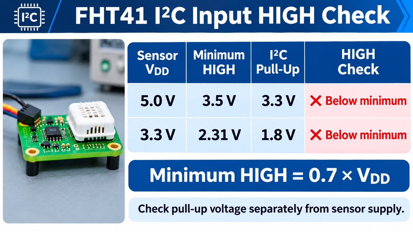
Check the sensor supply and the bus voltage separately. For example, a 3.3 V FHT41 supply is within range, but 1.8 V pull-ups fall below the calculated sensor input HIGH minimum of 2.31 V at nominal VDD (0.7 × 3.3 V). Resolve the logic levels before building on that board. On the prototype, measure SDA and SCL at both ends, including the signal rise time and the LOW and HIGH levels. If you use the integrated heater, capture the sensor rail during a pulse and check for voltage droop or unexpected resets. Confirm the heater timing for the exact FHT41 specification revision used in the build. FHT41 product specification
Can you reuse an SHT41 PCB and driver with FHT41?
PCB and driver reuse require separate checks: compare the mechanical drawings for board fit, then test the operations the application uses. The published pin assignment and 0xFD measurement command provide specific starting points.
PCB footprint and assembly
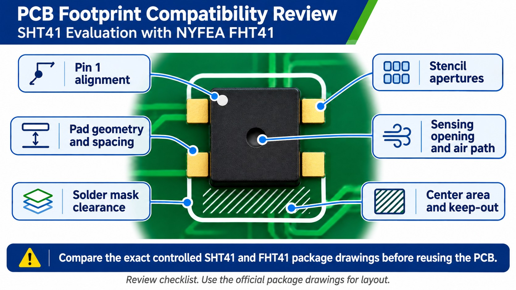
Align pin 1 on both approved drawings and compare pads, solder mask, stencil, center area and sensing opening. Check the package’s mounting requirements before placing the part.
Driver commands, timing and recovery
- Capture a known-good SHT41 transaction. Record the I²C address and speed, measurement command, time between write and read, six-byte response, and both CRC results. Check each setting against the FHT41 specification before reusing it, then capture the same sequence on the candidate board. Compare frame order, timing and how the driver converts raw counts. Use the shared reference to compare the final temperature and RH values.
- Exercise startup, read failure and recovery. Use the power-up and reset paths the product actually runs. Test a busy response, an incomplete frame and a CRC failure. Reject the failed sample. If the interface still displays the last valid value, keep its original timestamp and show that the current reading is unavailable. Check that a later valid sample clears the fault and updates both the value and timestamp.
- Record what passed and what changed. Keep the schematic revision, footprint revision, firmware build and test logs together. If a condition is still open, assign it a next action before the qualification build.
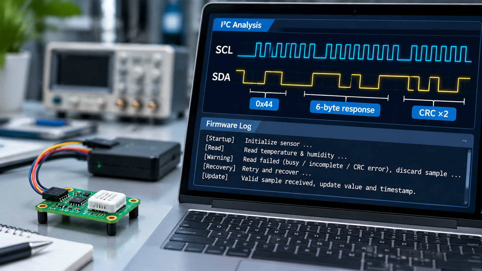
Use your captured trace as a baseline and the approved datasheet and drawing revisions as the design authority. SHT41 communication, commands and data format · SHT41 outline and land pattern · FHT41 package and interface specification
How do you decide whether FHT41 meets the finished device’s requirements?
Sensirion SHT41 and NYFEA FHT41 both list ±1.8 %RH typical sensor accuracy. That figure describes the component under specified conditions. Set a separate acceptance limit for the finished device. Choose checkpoints from your actual temperature and humidity range, then compare each assembled unit with an independent reference. Sensirion humidity accuracy curves · NYFEA FHT41 accuracy specifications
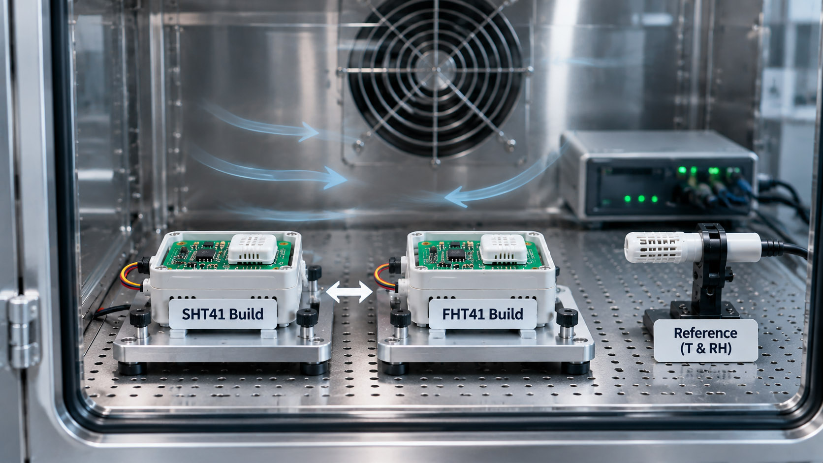
Place the SHT41 assembly, FHT41 assembly and reference probe in the same controlled environment. Match the enclosure, airflow, sampling and host workload. Agree on a stabilization rule before logging each assembly’s deviation from the reference. If the two assemblies disagree, swap their positions and repeat the check after stabilization. A difference that stays with the fixture position points to a setup effect, such as uneven airflow.
If response time matters, define the humidity step and the endpoint before the test, such as the time to enter and stay within the allowed error band. For a design that uses the heater, log recovery at the required operating conditions. Resume ambient readings once the assembly meets the project’s recovery criterion.
How would you apply a ±3.0 %RH product limit?
Suppose a room monitor must stay within ±3.0 percentage points of RH at 25 °C and 50% RH. Use the absolute deviation from the reference as the measured error. In this example, the comparison uncertainty is 0.4 percentage points. Treat the resulting interval as a pass if it lies entirely within the limit, a fail if it lies entirely beyond the limit, and inconclusive if it crosses the limit. Estimate the real uncertainty from the reference, repeatability and position effects.
| Absolute RH error | Decision at this checkpoint |
|---|---|
| 2.4 percentage points | Pass. The upper bound is 2.4 + 0.4 = 2.8, within the ±3.0 percentage point limit. |
| 2.8 percentage points | Inconclusive. The interval is 2.4–3.2 and crosses the limit. Improve the comparison before deciding. |
| 3.6 percentage points | Fail. The lower bound is 3.6 − 0.4 = 3.2, above the limit. Investigate the assembly and retest after a change. |
These values are hypothetical. Apply your approved decision rule and repeat the comparison across the conditions your product must meet.
| Record | Evidence for a decision |
|---|---|
| Test point and operating state | Reference temperature and RH, enclosure configuration, sample interval and host workload. |
| Error and response | Each assembly’s error against the reference, the comparison uncertainty, and the project’s response limit where applicable. |
| Decision and next action | Candidate meets this checkpoint, needs further evidence, or needs a design or firmware change. Retain the logs and repeat at all required checkpoints before release. |
What should you send NYFEA when requesting FHT41 samples?
For an initial enquiry, share the installed SHT41 order code, supply voltage, application and required temperature/RH accuracy. Ask for the FHT41-TR sample option, confirmed I²C address and current datasheet and package drawing.
For a detailed compatibility review, add the sensor and pull-up schematic, PCB land pattern, driver information and any available I²C trace. Include response-time, enclosure, membrane and exposure requirements. These details support the review; a completed prototype test is not needed to begin the discussion.
SHT41 is a Sensirion product. FHT41 is a NYFEA product. The evaluation applies to the exact part and assembled design tested.