SHT41 sensor Over Long I2C Cables: Wiring, Pull-Ups and ESP32 Troubleshooting
The SHT41 works on the desk. You move it into a cabinet or duct, extend the cable, and readings begin to disappear. The immediate decision is whether a connection change will fix the problem or the sensor needs a different remote link.
An SHT41 has no universal guaranteed I²C cable length. First compare short and extended wiring with the same one-sensor, heater-off setup at 100 kHz. Check remote power, the complete measurement transaction and signal quality. If direct I²C cannot meet those requirements on the installed route, evaluate a suitable extender or a controller near the sensor.
Start here: check the connection below, run the diagnostic sketch, and follow its status table. Use the pull-up calculation when the evidence points to an electrical problem. For initial bring-up, use the SHT41 Arduino ESP32 guide.
Start with the fault you can reproduce
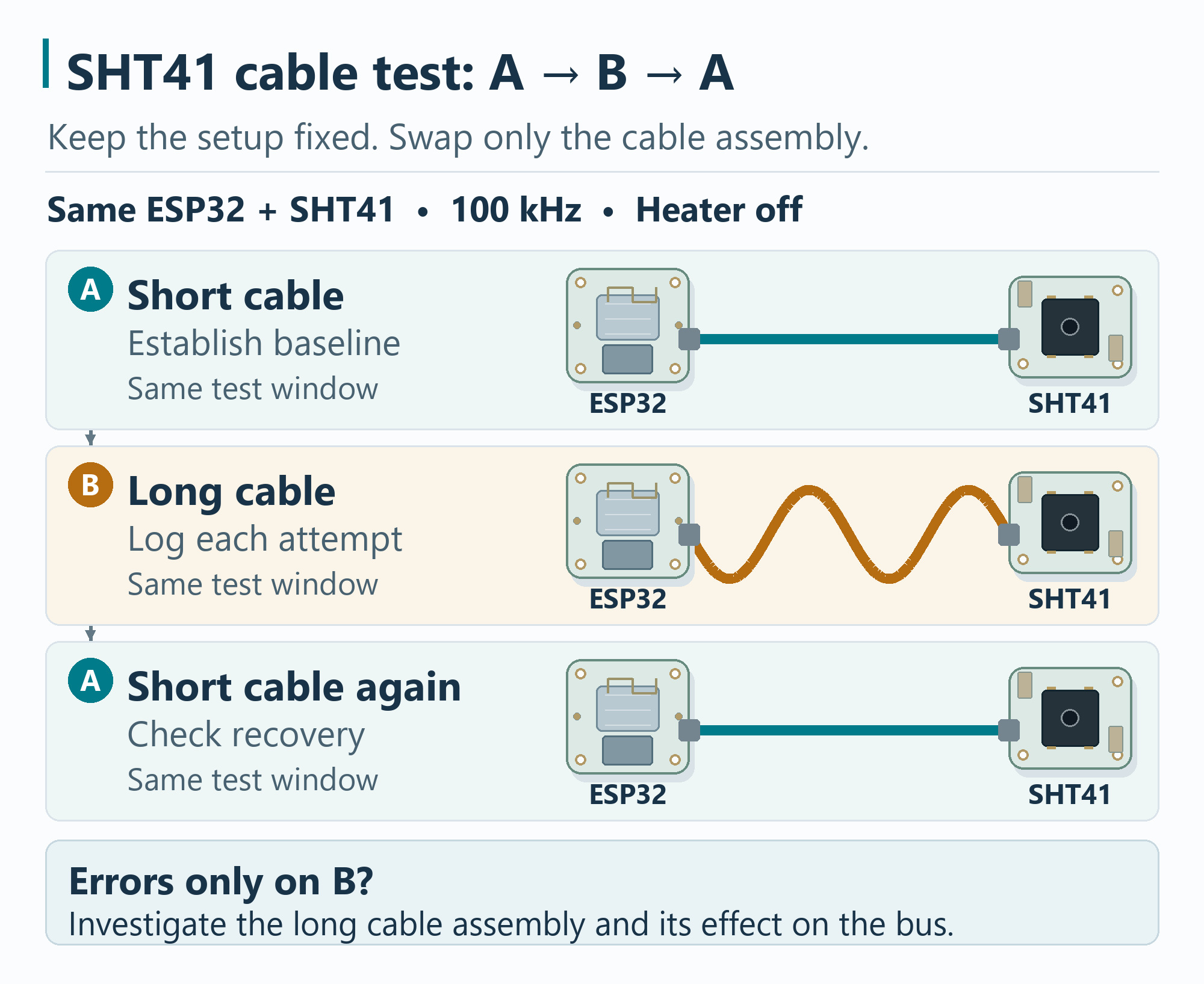
Keep one variable changing at a time so the result identifies a useful next action.
- Establish the short-cable baseline. Use one SHT41, a 100 kHz bus and heater-off measurements. Keep other I²C targets disconnected for this initial comparison. Confirm complete CRC-checked responses.
- Change only the cable assembly. Power down before rewiring. Keep the same sensor, firmware, supply, pull-ups and operating state; check connector mapping before restarting.
- Record each attempt on the extension. Distinguish a command failure, short response, CRC failure and a bus that remains low.
- Restore the original short assembly. If it now fails, investigate connectors, supply, damage or software state before assigning the fault to the extension.
- Compare equal test windows. Record attempts, failures and operating events for each assembly. A short/long/short result that follows the extension points to that cable assembly or its interaction with the circuit; it does not isolate length from connectors or routing.
Sensirion recommends keeping I²C wiring short because additional cable capacitance can degrade the signals. Its design guide identifies buffering or bus extension as options when longer connections are necessary. Sensirion design guide, section 4.4
Keep the first extended connection simple
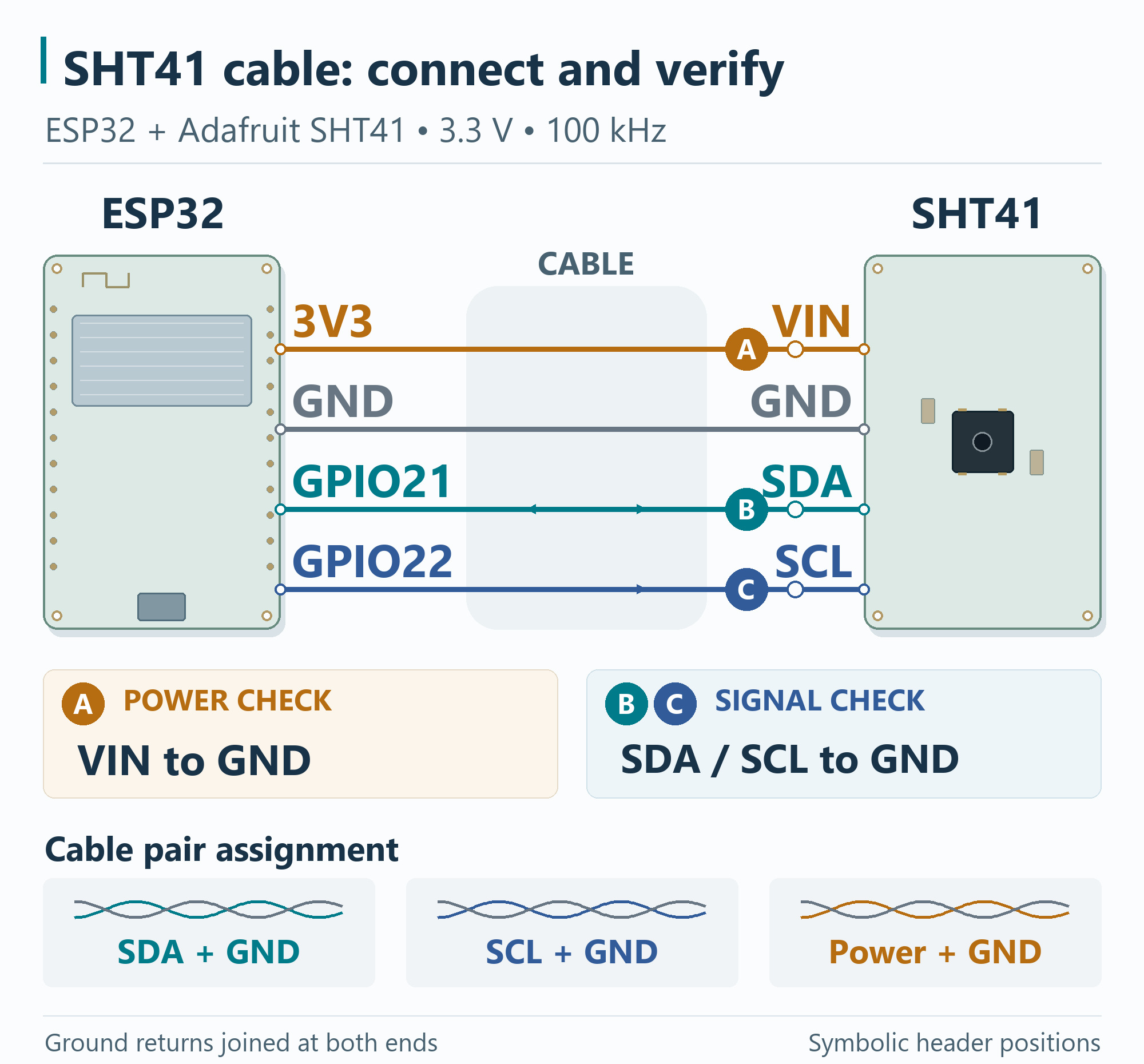
The reference configuration is a classic ESP32 DevKit and one Adafruit SHT41 breakout, connected through its labeled header pins. It is a documented wiring reference, not a tested cable-length specification. Use a common ground, 100 kHz and heater-off measurements.
| ESP32 side | Sensor side | Check |
|---|---|---|
| Regulated 3.3 V | VIN on this Adafruit board | Measure the input at the remote board during operation |
| GND | GND | Provide a continuous return path |
| GPIO21 | SDA | Check the connected pull-ups and their supply rail |
| GPIO22 | SCL | Check the connected pull-ups and their supply rail |
Adafruit documents a regulator, level-shifted SDA/SCL and 10 kΩ pull-ups. Its 3V pin is a regulator output; this example feeds VIN. These details apply to the named board. Check another breakout's schematic before copying the power connection or changing resistors. Adafruit pinouts
GPIO21/22 apply to the classic ESP32. Select the exact board's pins for ESP32-C3, ESP32-S3 or other variants. Arduino-ESP32 I²C API
Keep the bare sensor and signal rails within their limits. SHT41-AD1B uses address 0x44 and a 1.08–3.6 V sensor supply. A module's higher-voltage input rating does not establish the permissible ESP32 signal voltage. Sensirion SHT4x datasheet
For a direct, single-ended extension, route SDA with a nearby ground return and SCL with a nearby ground return. A cable with separate SDA/GND and SCL/GND twisted pairs is a useful starting arrangement. Verify the cable's capacitance for the actual assignment; cable construction and shielding also affect the electrical load.
Keep the route away from motor wiring, relay contacts and switching power nodes. A shield may help with interference, but it does not correct an inadequate supply, excessive capacitance or an incorrect connector.
Measure power at the far end, across the remote board's input and ground; check the sensor supply when accessible. Cable resistance and regulator headroom can matter even when the ESP32 rail looks stable. Use the module's specified local decoupling. A meter can reveal steady voltage drop; brief disturbances may require a scope. Test heater operation separately if the application uses it.
Run a complete SHT41 link test
An address scan cannot establish reliable measurement delivery. This sketch sends a fresh 0xFD command for each attempt, waits 10 ms, reads six bytes and checks both CRCs. It reports a CSV row approximately once per second, with no automatic retry or reset. Failures remain visible.
Use Arduino IDE with the Arduino-ESP32 board package and the correct board selected. No sensor library is required. Power-cycle the sensor before testing, open Serial Monitor at 115200 baud, and set RUN_LABEL to identify each cable assembly. On another ESP32 variant, change SDA_PIN and SCL_PIN.
The sensor protocol follows the SHT4x datasheet; pin, clock and timeout calls follow the Arduino-ESP32 API. The 50 ms timeout bounds driver waiting; it does not improve electrical signals. This diagnostic implementation has been source-reviewed; ESP32 compilation and physical cable tests have not been performed.
Open the complete Arduino-ESP32 diagnostic sketch
#include <Arduino.h>
#include <Wire.h>

constexpr int SDA_PIN = 21, SCL_PIN = 22;
constexpr uint8_t SENSOR = 0x44;
constexpr uint32_t CLOCK_HZ = 100000, INTERVAL_MS = 1000;
constexpr char RUN_LABEL[] = "short_a"; // Use letters, digits and underscores.

uint32_t attempts = 0, failed = 0, lastStart = 0;
uint32_t lastValid = 0, maxGap = 0;
bool haveValid = false;

uint8_t crc8(const uint8_t* data) {
  uint8_t crc = 0xFF;
  for (int i = 0; i < 2; ++i) {
    crc ^= data[i];
    for (int bit = 0; bit < 8; ++bit) {
      crc = (crc & 0x80) ? uint8_t((crc << 1) ^ 0x31)
                         : uint8_t(crc << 1);
    }
  }
  return crc;
}

struct Sample {
  const char* status = "WRITE_FAIL";
  int tx = -1, crcT = -1, crcRH = -1;
  size_t bytes = 0;
  float temperature = 0, humidity = 0;
  bool valid = false;
};

Sample measure() {
  Sample s;
  // One controller task owns this bus. No GPIO drives a line high.
  if (digitalRead(SDA_PIN) == LOW || digitalRead(SCL_PIN) == LOW) {
    s.status = "BUS_LOW";
    return s;
  }
  Wire.beginTransmission(SENSOR);
  if (Wire.write(uint8_t(0xFD)) != 1) {
    s.status = "BUFFER_FAIL";
    return s;
  }
  s.tx = Wire.endTransmission(true);
  if (s.tx != 0) return s;
  delay(10);
  s.bytes = Wire.requestFrom(SENSOR, size_t(6), true);
  if (s.bytes != 6 || Wire.available() != 6) {
    while (Wire.available()) Wire.read();
    s.status = "SHORT_READ";
    return s;
  }
  uint8_t b[6];
  for (int i = 0; i < 6; ++i) b[i] = uint8_t(Wire.read());
  s.crcT = (crc8(b) == b[2]) ? 1 : 0;
  s.crcRH = (crc8(b + 3) == b[5]) ? 1 : 0;
  if (s.crcT != 1 || s.crcRH != 1) {
    s.status = "CRC_FAIL";
    return s;
  }
  const uint16_t rawT = (uint16_t(b[0]) << 8) | b[1];
  const uint16_t rawRH = (uint16_t(b[3]) << 8) | b[4];
  s.temperature = -45.0f + 175.0f * rawT / 65535.0f;
  s.humidity = -6.0f + 125.0f * rawRH / 65535.0f;
  s.valid = true;
  s.status = "VALID";
  return s;
}

void setup() {
  Serial.begin(115200);
  const uint8_t check[2] = {0xBE, 0xEF};
  if (crc8(check) != 0x92 || !Wire.begin(SDA_PIN, SCL_PIN, CLOCK_HZ)) {
    Serial.println("SETUP_FAIL: CRC self-check or I2C initialization");
    while (true) delay(1000);
  }
  Wire.setTimeOut(50);
  delay(20);
  Serial.println("label,clock_hz,ms,attempt,status,tx,bytes,crc_t,crc_rh,"
                 "temp_c,rh_raw_pct,failed,fail_pct,age_ms,max_gap_ms");
}

void loop() {
  const uint32_t started = millis();
  if (uint32_t(started - lastStart) < INTERVAL_MS) return;
  lastStart = started;
  ++attempts;
  const Sample s = measure();
  const uint32_t completed = millis();
  if (haveValid) {
    const uint32_t gap = completed - lastValid;
    if (gap > maxGap) maxGap = gap;
  }
  if (s.valid) {
    lastValid = completed;
    haveValid = true;
  } else {
    ++failed;
  }
  Serial.printf("%s,%lu,%lu,%lu,%s,%d,%u,%d,%d,", RUN_LABEL,
                (unsigned long)CLOCK_HZ, (unsigned long)completed,
                (unsigned long)attempts, s.status, s.tx,
                (unsigned)s.bytes, s.crcT, s.crcRH);
  if (s.valid) Serial.printf("%.3f,%.3f,", s.temperature, s.humidity);
  else Serial.print("NA,NA,");
  Serial.printf("%lu,%.4f,", (unsigned long)failed,
                100.0 * double(failed) / double(attempts));
  if (haveValid) {
    Serial.printf("%lu,%lu\n", (unsigned long)(completed - lastValid),
                  (unsigned long)maxGap);
  } else {
    Serial.println("NA,NA");
  }
}
The CRC self-check uses the manufacturer's published BEEF → 92 vector. The code never prints an old temperature/RH as a new measurement. RH is logged before clipping; formula outputs outside 0–100%RH are nonphysical and require interpretation. They do not become valid environmental readings merely because the frame passes CRC.
Read the status, then choose the next check
| Status | Meaning | Next check |
|---|---|---|
BUS_LOW |
A line was low before the attempt | Inspect idle levels, unpowered boards and shorts; isolate the branch |
WRITE_FAIL |
Command transmission returned an error | Keep tx for diagnosis; check address, power, wiring and signal levels |
SHORT_READ |
A complete response was not received | Check conversion timing, remote power and the read waveform |
CRC_FAIL |
At least one measurement word failed CRC | Check crc_t/crc_rh; compare cable routing and signals |
VALID |
Both measurement words passed CRC | Continue the run; assess measurement accuracy separately |
BUFFER_FAIL |
The local command was not buffered | Investigate controller/software state before blaming the cable |
crc_t and crc_rh are 1 = pass, 0 = fail, −1 = untested. tx = −1 means transmission was not attempted; nonnegative values come from endTransmission(). These labels identify a failed stage, not its physical cause.
Compare failure rate and data gaps together. failed / attempt is the first-attempt failure rate because this program does not retry. age_ms is the age of the last CRC-valid sample; it is zero after success and NA before the first success. max_gap_ms includes failed periods after the first success, so a connection that goes offline cannot conceal the growing gap. No initial acquisition time is included in that metric.
Statistics reset on reboot. Use the timestamps for actual timing; the nominal one-second schedule can slip during blocked operations. Keep individual runs shorter than the roughly 49.7-day millis() wrap period. Save the log and record the Arduino-ESP32 version, cable, pull-ups and operating conditions alongside it.
If reducing a faster clock to 100 kHz helps, investigate timing margin. Do not shorten the sensor's conversion wait: the SHT41 can NACK while busy, and a result is consumed by an acknowledged read. Every new attempt in the sketch therefore begins with a fresh measurement command.
Check the physical event that accompanies the failure
If failures follow a relay, motor or other load switching, capture remote power and signals during that event. A supply disturbance and signal coupling can occur together. Compare the route away from the load while keeping the rest of the setup fixed.
With a scope, inspect SDA/SCL at both ends relative to local ground. Measure rise time between 30% and 70% of the pull-up voltage, low-level voltage and ringing. Use a suitable probe with a short return; it adds load. Ground clips on a grounded bench scope are normally connected together, so check the grounding arrangement before probing separated nodes; use an appropriate differential probe when needed.
A logic analyzer can locate missing acknowledgments and incomplete transfers, but cannot establish analog margin from a digital trace alone. Without a scope, use short/extended cable and quiet/load-switching comparisons to narrow the fault; electrical compliance remains unverified.
If the bus stays low
Check for shorts and unpowered boards before adding a software recovery loop. NXP describes bus-clear clocking for SDA stuck low and reset or power cycling when appropriate. Such recovery must release lines through open-drain behavior and respect ownership of the bus. Never drive a held-low line high with a push-pull GPIO. NXP bus-clear procedure, section 3.1.16
After recovery, start a fresh sensor transaction and retain the failure in the log. A recurring recovery event is evidence that the connection still needs investigation.
Choose pull-ups after identifying the electrical problem
I²C devices pull SDA and SCL low; pull-up resistors let the lines rise again. Added capacitance slows that rise. Reducing resistance can speed it up, but increases the current required to hold the line low. Both edges of the design problem matter: a valid high must arrive in time, and a valid low must remain low enough.
For a simple resistor-capacitor approximation:
tr ≈ 0.8473 × Rp × Cb
Rp(max) ≈ tr(max) / (0.8473 × Cb)
Rp(min) ≈ (Vpullup − VOL(max)) / IOL
Rp is the effective pull-up resistance on one signal. Cb is that signal's total capacitance, including cable, boards, connectors and probes. VOL(max) and IOL are a device's guaranteed low-level voltage and corresponding sink current. Check every relevant output; the most restrictive bound governs the simple shared-rail design. A level-shifted breakout adds interface behavior, so this model does not replace its schematic and measured waveform. TI pull-up calculation note
A 300 pF example: why 4.7 kΩ can be too weak
Assume a cable contributes 100 pF per metre on the relevant signal path. A 2 m cable contributes 200 pF, and an assumed 100 pF from the remaining connection gives 300 pF total. These are illustrative inputs, not measurements. Use the cable's capacitance for the chosen conductor assignment, plus the actual boards and connectors.
NXP specifies maximum rise times of 1,000 ns for Standard-mode and 300 ns for Fast-mode. NXP UM10204, Table 11
| Effective pull-up | Calculated rise time at 300 pF | Compared with the 1,000 ns Standard-mode limit |
|---|---|---|
| 10 kΩ | 2,542 ns | Exceeds the limit |
| 4.7 kΩ | 1,195 ns | Exceeds the limit |
| 2.2 kΩ | 559 ns | Below this rise-time limit only |
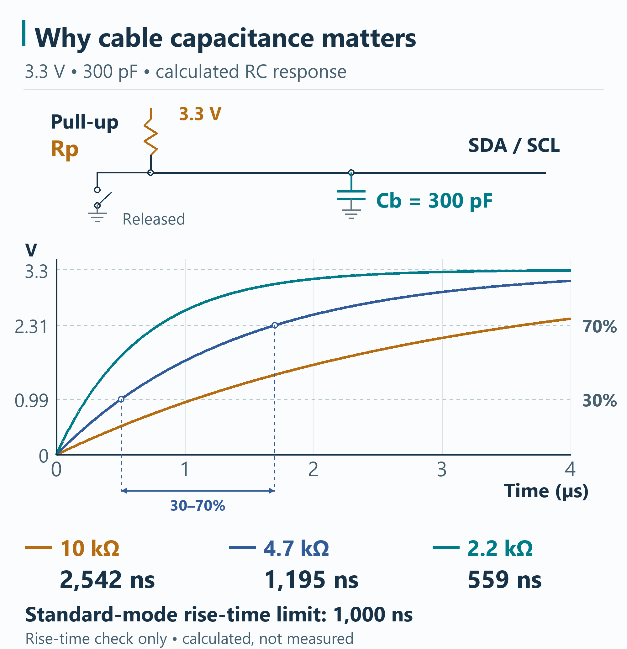
The calculated upper resistance is about 3.93 kΩ at 100 kHz, or 1.18 kΩ at 400 kHz. This changes the decision: at the assumed load, another 4.7 kΩ recommendation would not resolve the rise-time requirement.
For the lower bound, suppose a connected output is guaranteed to sink 3 mA at or below 0.4 V. A 3.3 V pull-up gives (3.3 − 0.4) / 0.003 ≈ 967 Ω. This is a hypothetical drive limit, not the asserted SHT41 or ESP32 rating. For the real circuit, check the devices' guaranteed limits, supply variation and resistor tolerances before choosing a value.
If no resistance range satisfies both requirements with margin, stop adding stronger pull-ups. Reduce the electrical load or evaluate a suitable buffer/remote architecture. Even when a range exists, verify the assembled waveform: the RC model does not describe every reflection or coupled transient.
Count installed pull-ups before adding another
Two 10 kΩ pull-ups connected to the same rail on one continuous signal path give 5 kΩ effective resistance. An additional resistor changes that total again. Inspect the boards and schematic before modifying them.
Moving a resistor to the far end does not remove the cable's capacitance. With active buffers or switches, evaluate the selected segments and device requirements instead of treating all resistors as one simple parallel network.
When should you change the connection architecture?
Keep direct I²C when the installed assembly meets electrical and application requirements. The following observations tell you when to change course:
- No acceptable pull-up window: reduce capacitance or evaluate an appropriate buffered link.
- Adequate edges in quiet conditions, failures around load switching: investigate power and coupling first; consider differential transport when the route cannot be made suitable.
- Separated power domains or significant ground differences: assess reference limits and isolation requirements before choosing a link. A differential buffer alone does not establish isolation.
- Many remote points or excessive data age after faults: assess local controllers and a transport with explicit recovery and freshness handling.
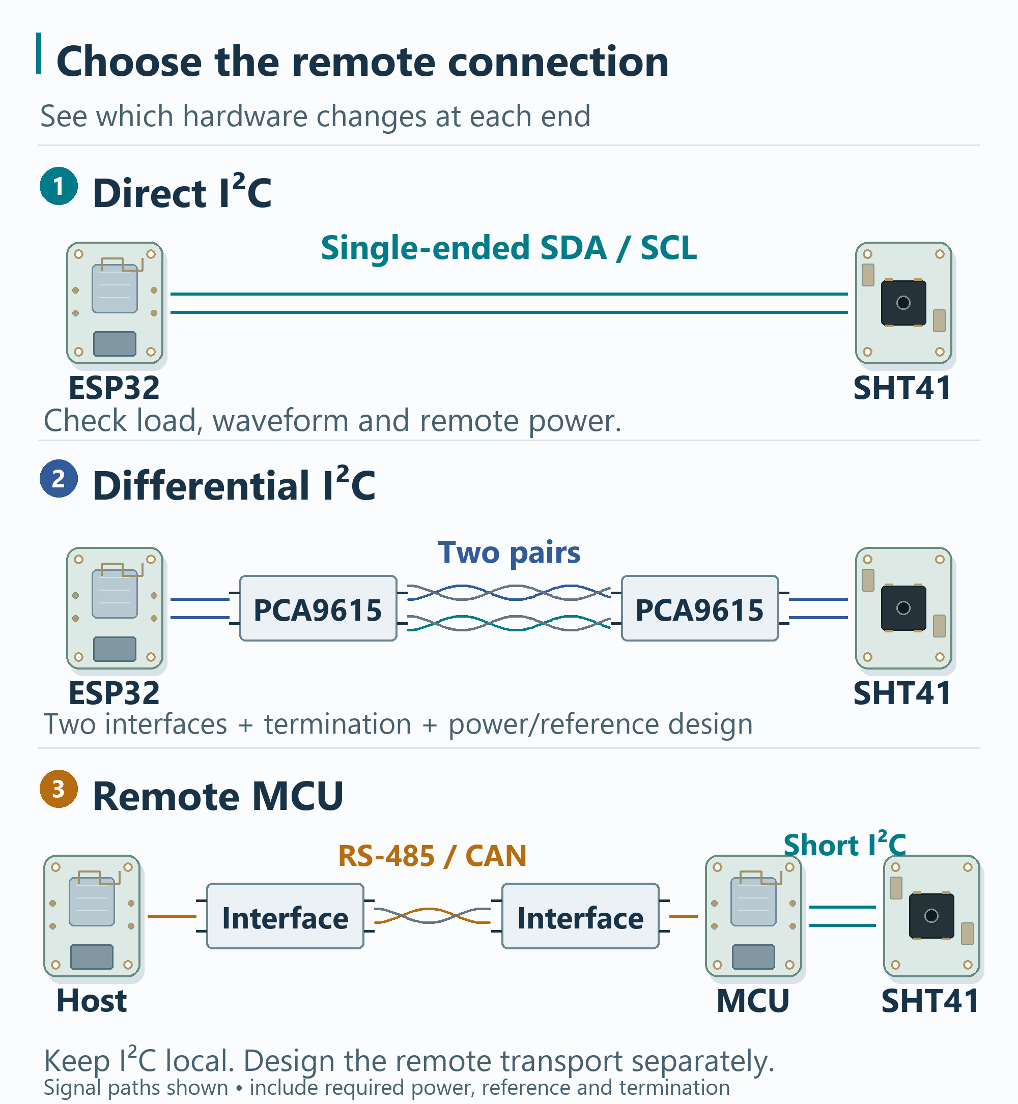
| Approach | What it addresses | What still needs checking |
|---|---|---|
| Direct I²C | A simple connection between the controller and nearby sensor | Entire bus load, voltage, timing, routing and recovery |
| TCA9548A channel selection | Independent access to same-address sensors and disconnection of unselected branches | The selected path's capacitance and timing; it provides no active edge regeneration |
| Suitable I²C buffer | Separation of supported capacitive segments | Device compatibility, low-level offsets, delay and allowed topology |
| Differential I²C extension | A differential physical link between local I²C segments | Supplies, termination, cable, reference/common-mode limits and end-to-end timing |
| MCU near the SHT41 | A short sensor bus with a separate remote communications link | Local power, firmware, timestamps, transport and stale-data handling |
A TCA9548A does not turn an I²C branch into a long-distance link. Its pass switches connect selected channels; the selected cable still has to meet the system's electrical requirements. For address routing, use the multiple-SHT41 development guide. TI TCA9548A datasheet
For differential extension, a device such as NXP PCA9615 translates local SDA/SCL into differential signals and back at the remote end. The implementation needs compatible interfaces at both ends and the specified termination and supply arrangement. It does not provide galvanic isolation. Keep each single-ended section short and check compatibility with any additional buffers. NXP PCA9615 datasheet
For sensors distributed around a building, an MCU near each sensor keeps the sensor bus local. RS-485, CAN or wireless then needs its own power, transport and recovery design.
Validate the installed cable before relying on the readings
Start with the application's decision: how old can a reading become before the display, controller or alarm should treat it as unavailable? A room display and a ventilation controller can have different requirements.
Write down the maximum data age, permitted first-attempt failure rate, recovery time and unavailable-data behavior. These are application requirements, not numbers supplied by the SHT41 datasheet. They determine whether an apparently working extension is useful.
Then test the actual assembly:
- Use the intended cable and connectors. Record length, part number, conductor assignment, pull-ups, supply and clock.
- Exercise normal operating states. Include startup, controller activity and nearby loads switching. Add heater tests separately if it is used.
- Log every attempt and recovery. Do not substitute the previous valid sample without marking its age.
- Check power and signals under the critical conditions. Repeat after a cable, board or pull-up change.
- Verify measurement placement. Once communication is stable, confirm that the sensor measures the intended air. Use the enclosure and airflow guide for the physical placement checks.
For scale, 10,000 attempts at one-second intervals take about 2 hours 47 minutes. Choose test duration and operating states for the application; a fault-free run covers only the tested conditions.
Record each test condition separately. A single overall failure percentage can hide a burst of lost samples whenever a relay switches. Judge both failure count and the longest gap between valid samples against the application's limits. If the sensor supplies an actuator, define what happens during that gap rather than silently reusing an old reading.
Save the CSV with the cable/connector identity, effective pull-ups, clock, supply checks and tested operating states. Repeat the short-cable run after a failure on the extension. Use the comparison to retain, correct or replace the remote connection.
Frequently asked questions
Can I run an SHT41 over a 1 m, 2 m or 5 m cable?
SHT41 has no general guarantee for those distances. Use the actual cable load, remote supply, signal measurements and logged transactions to evaluate the installation. A probe advertised with a particular cable length represents that assembly; it does not establish a rating for an arbitrary SHT41 circuit.
Which pull-up resistor should I use for a long SHT41 cable?
Choose the effective I²C pull-up resistance from the bus capacitance, rise-time limit and device sink-current limits. In the 300 pF example at 100 kHz, 4.7 kΩ gives a calculated 1,195 ns rise time, above the 1,000 ns Standard-mode limit. At the same load, 2.2 kΩ gives 559 ns. Check the low-level voltage and confirm both edges on the assembled bus before using that value.
Does a CAT5 or CAT6 cable make SHT41 communication reliable?
A twisted-pair cable can provide useful routing and return paths, but the category name does not qualify an I²C installation. Check the actual assignment, capacitance, remote supply and signal waveform. Direct I²C and differential I²C require different pair assignments. Using network cable does not turn the connection into Ethernet.
Why does the scanner find SHT41 while the read still fails?
An I²C scanner can find the SHT41 at 0x44 after an address acknowledgment. A measurement also needs a valid command, conversion time and a six-byte response with two valid CRCs. Use the diagnostic sketch to separate command-write errors, short reads and CRC errors. Check conversion timing before attributing a failure to the cable.
Will a TCA9548A fix long SHT41 cables?
A TCA9548A can select between SHT41 sensors that share an address. It is a pass switch, so the selected branch still needs to meet I²C timing and loading limits. For an overloaded branch, evaluate a suitable I²C buffer, differential extender or controller near the sensor.
Can a long cable make SHT41 humidity gradually read lower?
Digital I²C wiring is not an analog humidity signal whose amplitude directly represents RH. Investigate missing transfers and CRC failures as communication symptoms. For repeatedly CRC-valid but shifted readings, check local temperature, sensor placement, supply conditions and the measurement reference. CRC validity alone does not establish measurement accuracy, but a stable offset should not automatically be treated as cable attenuation.
Planning a remote temperature and humidity product?
For a useful design inquiry, include the cable length and part number, wiring, board schematic, supply, clock and diagnostic CSV. State the longest allowed gap without a valid reading. Those details help define the connection and sensor evaluation requirements.
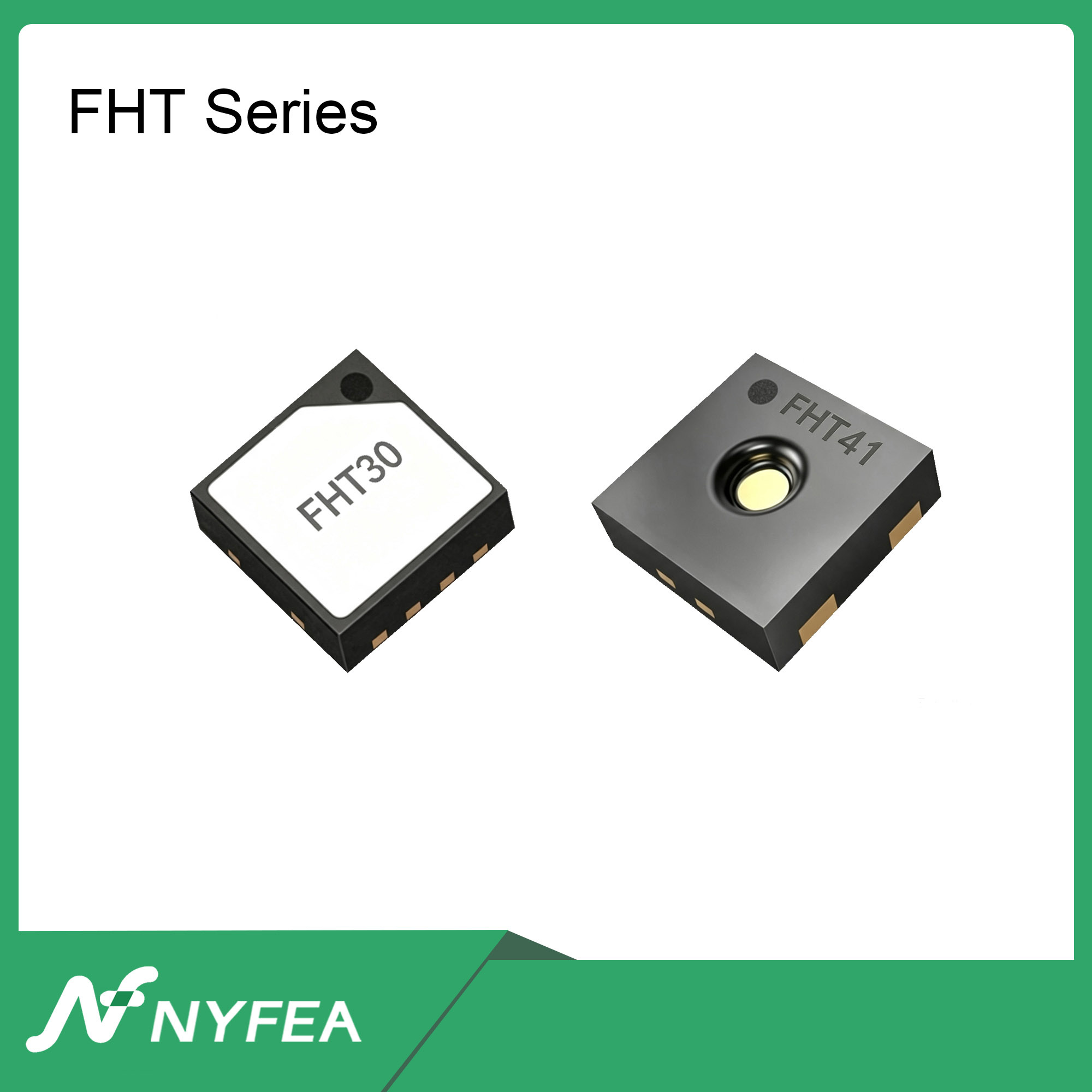
If you are evaluating a new sensor board, NYFEA FHT41 can be considered against your controlled electrical, interface, package and measurement requirements. This SHT41 analysis does not establish FHT41 compatibility or a cable-length rating. Discuss the application with NYFEA.
Technical references
- Sensirion SHT4x datasheet, Version 7.3, June 2026 — device identity, supply, transaction and timing requirements.
- Sensirion Design Guide for Humidity and Temperature Sensors, Version 2, March 2024 — cable, grounding and installation considerations.
- NXP UM10204, Rev. 7.0, October 2021 — bus timing and bus-clear behavior.