SHT41 Humidity Monitor with STM32F407: Fan Control and Sensor Fault Handling
An SHT41 measures humidity inside an equipment cabinet, and an STM32F407 controls the fan. At a 70% RH setpoint, alternating readings of 69.8% and 70.2% make the fan toggle repeatedly. Then a sensor read fails. What should the fan do? ±1.8% / max. ±2.5% RH Digital humidity and temperature sensor In line with Sensirion’s industry-proven humidity and temperature sensors, the SHT41 offers the best price-performance ratio on the market. Tape and reel packaging combined with its suitability for standard SMD assembly processes make the SHT41 ideal for high-volume applications.
Fan control. In this SHT41 and STM32F407 example, start the auxiliary fan at 70% RH or higher and stop it at 65% RH or lower. Keep the current command between those thresholds.
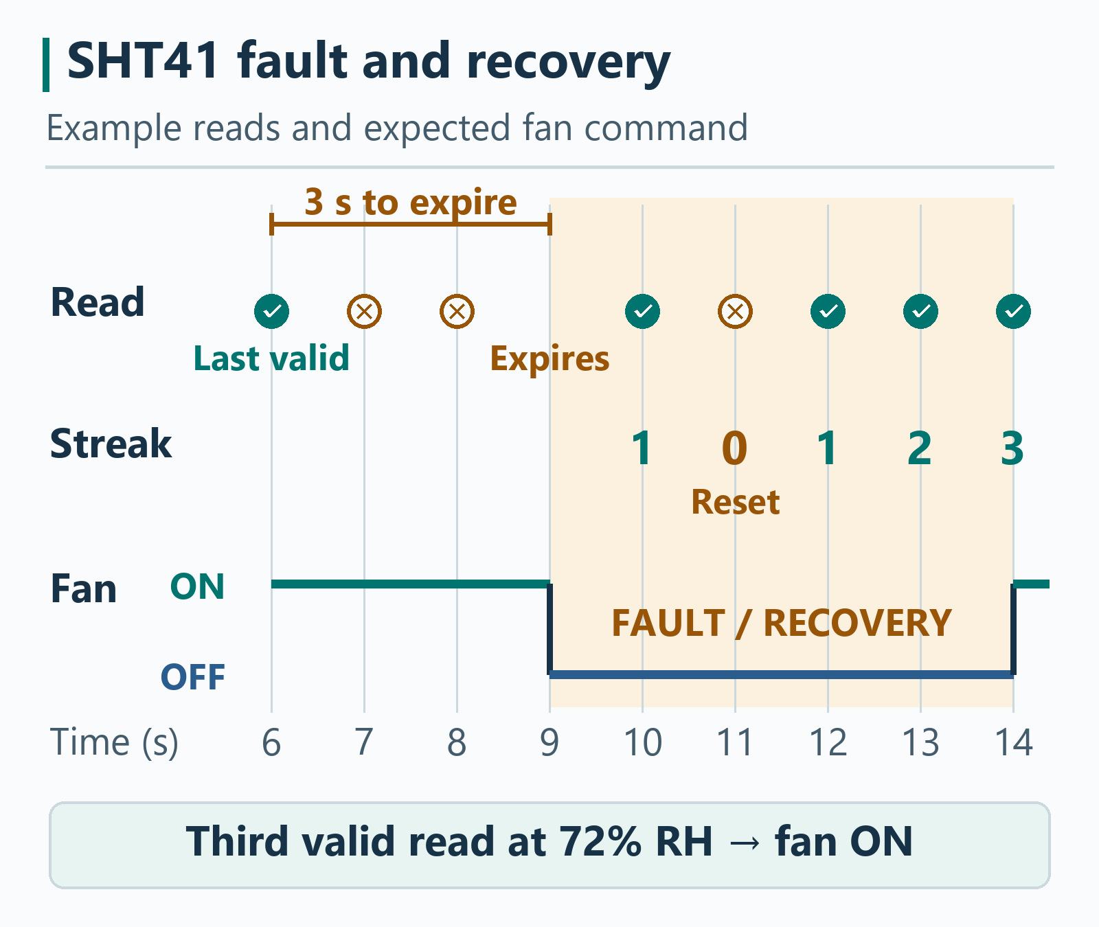
Sensor fault. Poll once per second. Switch the auxiliary fan off when the last valid reading is 3 seconds old. At startup and after a fault, require three consecutive valid readings before applying the start threshold.
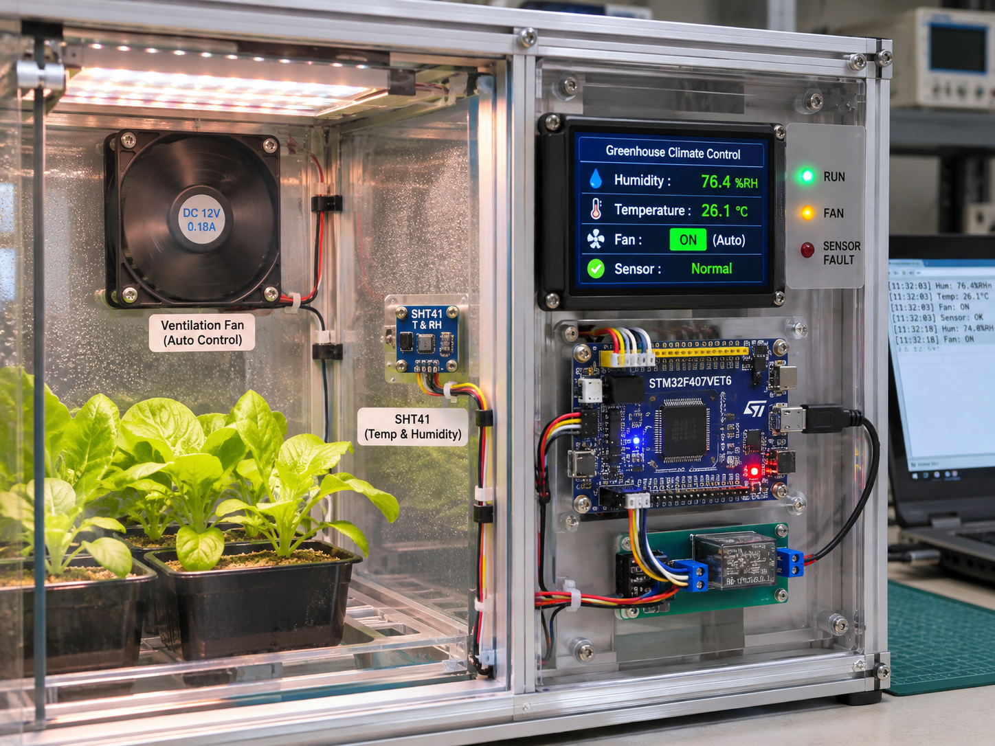
This reference design is for firmware and hardware engineers building a low-voltage equipment cabinet monitor. The fan is for auxiliary ventilation, with essential cooling handled separately. Use the example settings to test your control logic, then set the thresholds and fault output for your cabinet.
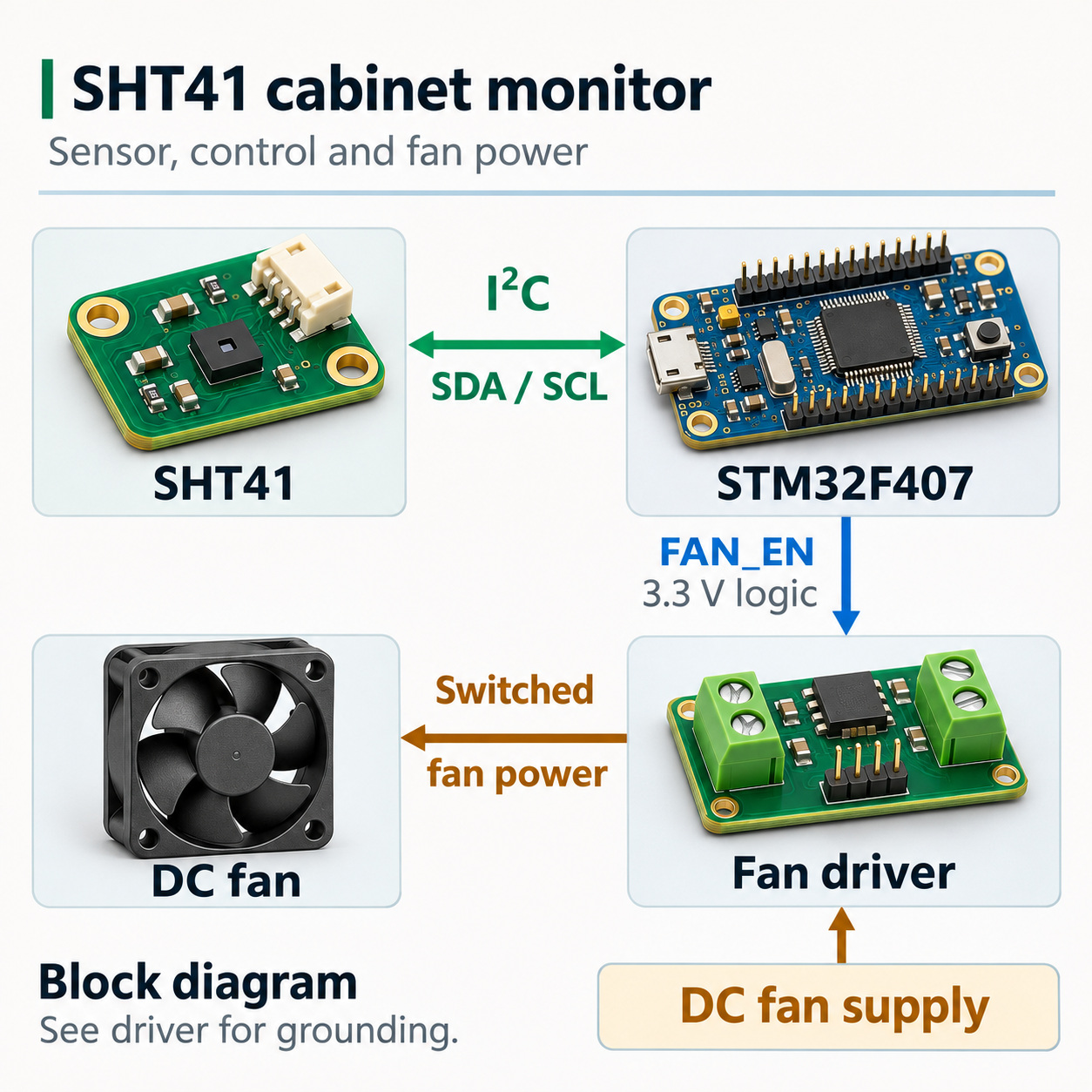
1. Connect the SHT41, STM32F407 and fan driver
Start with an STM32F407 board, one SHT41 breakout and a short I²C connection. Follow the STM32F407 SHT41 wiring and HAL driver guide to bring up the bus. The example below calls that guide’s SHT41_Read() function.
On the standard SHT41 at 7-bit address 0x44, the driver sends 0xFD, waits 10 ms in this implementation and reads six bytes. The read counts as valid only if the transfer completes and both CRC checks pass. A failed attempt leaves the last-valid timestamp untouched. This distinction matters because the control loop can keep running even when the sensor stops providing data. Sensirion SHT4x datasheet, Figure 1 and command table
Use a separately powered low-voltage fan and a driver with a 3.3 V-compatible logic input. In the code, FAN_EN is an active-high command, so configure its output to start low. Follow the selected driver’s grounding and protection requirements, and verify the fan command stays inactive while the MCU pin is in its reset state. The GPIO supplies the command and the fan supply powers the load.
Place the SHT41 where it measures the air you intend to control. Keep it away from the power regulator, hot surfaces and the fan’s immediate discharge. Log temperature with RH and compare readings with the fan both off and on. A change in local airflow or sensor temperature can shift RH even when the cabinet’s moisture content barely changes. Sensirion sensor design guide, thermal and housing considerations
2. How do two RH thresholds prevent rapid fan switching?
Start the fan at 70% RH and stop it at 65% RH in this example. The resulting 5 percentage-point hysteresis band holds the current state between those limits. At 68% RH while rising from a dry state, the fan stays off. At 68% RH after the fan has started, it stays on.
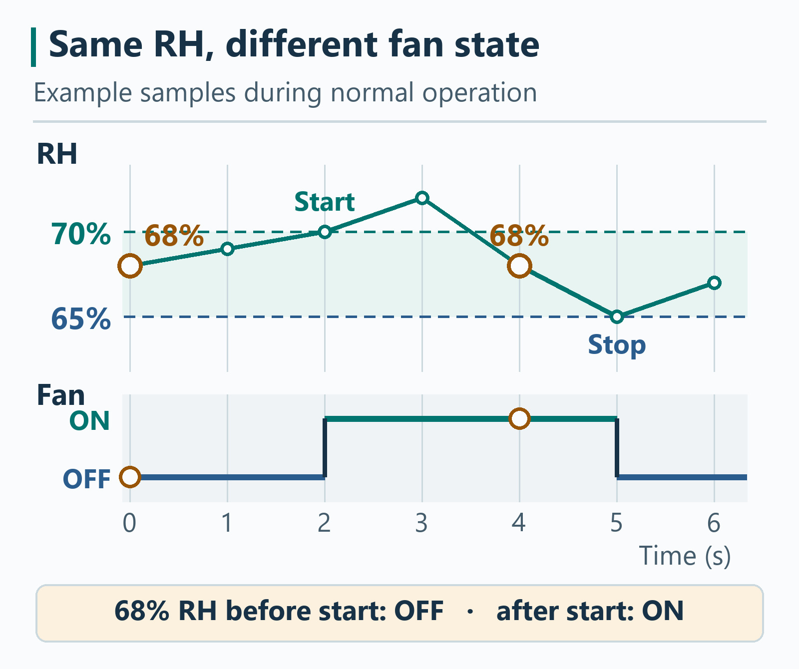
| Latest valid RH | Fan currently off | Fan currently on |
|---|---|---|
| 70% RH or higher | Turn on | Stay on |
| Above 65% and below 70% RH | Stay off | Stay on |
| 65% RH or lower | Stay off | Turn off |
Choose the band after looking at the variation of a correctly installed sensor around the desired control point. If one operating cycle swings through both limits, inspect fan placement, sensor exposure and cabinet response before widening the band. A band chosen to suppress noise cannot correct a systematic placement error.
3. What should the fan do if the SHT41 stops responding?
Keep the previous fan command through a short interruption, then apply a defined fallback when the last valid reading expires. In this design, the STM32F407 enters FAN_FAULT and commands the auxiliary fan off when the last valid reading reaches 3,000 ms old. The same deadline detects a sensor that never responds after boot. A failed attempt does not refresh the reading’s age.
| Condition | Fan command | Controller behavior |
|---|---|---|
| Starting, fewer than three consecutive valid reads | Off | Wait for stable communication |
| Valid reads in normal operation | Apply hysteresis | Refresh the last-valid timestamp |
| Failed read, last valid reading still under 3 seconds old | Hold prior command | Log the failure, preserve the timestamp |
| Data age reaches 3 seconds | Off in this example | Report FAN_FAULT |
| Valid reads return after a fault | Off until the third consecutive valid read | Restart from off and apply the start threshold |
For example, a recovered reading of 68% RH leaves the fan off even if it was running before the fault. At 72% RH, the third consecutive valid reading can start it again. A failed read during recovery resets the streak.
Choose the fallback independently of the humidity thresholds. If the same fan provides essential cooling, design an independent temperature control or protection path and verify its behavior during sensor, firmware and power faults. The off state in this example applies to the auxiliary fan.
How should you choose the SHT41 timeout?
Set the timeout above the longest expected gap between valid readings and below the time the equipment can tolerate stale data. With one-second polling, one missed poll creates a gap of about two seconds if the following read succeeds on schedule. The example’s three-second limit leaves about one second for timing variation in that case.
For the installed system, budget the time from the last valid read to the physical FAN_EN change. Include the longest delay before the firmware can service an expired reading. If that time exceeds the equipment requirement, revise the timeout together with the polling and blocking intervals, then repeat the fault test.
4. Implement the controller in STM32CubeF4 HAL
Place this block in main.c above main() in a CubeMX user-code area. Keep the SHT41 driver from the bring-up guide, include the generated main.h and label the active-high GPIO FAN_EN in CubeMX. FanMode is the controller’s observable state for logging or a fault indicator.
Open the STM32CubeF4 fan controller code
#include "main.h"
#include <stdbool.h>
#include <stdint.h>

bool SHT41_Read(float *temperature_c, float *humidity_rh);

enum {
    SAMPLE_MS = 1000U,
    STALE_MS = 3000U,
    RECOVERY_SAMPLES = 3U
};

typedef enum { FAN_WAIT, FAN_OFF, FAN_ON, FAN_FAULT } FanMode;

typedef struct {
    FanMode mode;
    uint32_t last_valid_ms;
    uint32_t last_poll_ms;
    uint8_t valid_streak;
} FanControl;

static void Fan_Expire(FanControl *fan, uint32_t now)
{
    if ((uint32_t)(now - fan->last_valid_ms) >= STALE_MS) {
        fan->mode = FAN_FAULT;
        fan->valid_streak = 0U;
    }
}

static void Fan_AcceptAttempt(FanControl *fan, uint32_t now,
                              bool read_ok, float rh)
{
    Fan_Expire(fan, now);

    if (!read_ok || !(rh >= 0.0f && rh <= 100.0f)) {
        fan->valid_streak = 0U;
        return;
    }
    fan->last_valid_ms = now;

    if (fan->mode == FAN_WAIT || fan->mode == FAN_FAULT) {
        if (++fan->valid_streak < RECOVERY_SAMPLES) {
            return;
        }
        fan->mode = FAN_OFF;
        fan->valid_streak = 0U;
    }

    if (fan->mode == FAN_OFF && rh >= 70.0f) {
        fan->mode = FAN_ON;
    } else if (fan->mode == FAN_ON && rh <= 65.0f) {
        fan->mode = FAN_OFF;
    }
}

static void Fan_WriteOutput(FanMode mode)
{
    HAL_GPIO_WritePin(FAN_EN_GPIO_Port, FAN_EN_Pin,
                      mode == FAN_ON ? GPIO_PIN_SET : GPIO_PIN_RESET);
}

static void Fan_Service(FanControl *fan)
{
    uint32_t now = HAL_GetTick();
    Fan_Expire(fan, now);
    Fan_WriteOutput(fan->mode);

    if ((uint32_t)(now - fan->last_poll_ms) < SAMPLE_MS) {
        return;
    }
    fan->last_poll_ms = now;

    float temperature_c = 0.0f;
    float humidity_rh = 0.0f;
    bool read_ok = SHT41_Read(&temperature_c, &humidity_rh);
    now = HAL_GetTick();
    Fan_AcceptAttempt(fan, now, read_ok, humidity_rh);
    Fan_WriteOutput(fan->mode);

    /* Log now, fan->mode and whether the read passed the same validity checks.
       Include temperature_c and humidity_rh only for a valid reading. */
}
After CubeMX initializes GPIO and I²C, initialize the controller and call its service function continuously from the main loop:
uint32_t now = HAL_GetTick();
FanControl fan = {
    .mode = FAN_WAIT,
    .last_valid_ms = now,
    .last_poll_ms = now - SAMPLE_MS
};
Fan_WriteOutput(fan.mode);

while (1) {
    Fan_Service(&fan);
    /* Run other short, nonblocking application tasks here. */
}
Check staleness between polls. The 3-second limit uses elapsed milliseconds, so it still works when a poll runs late. A valid read that arrives after the limit starts a new recovery streak. The unsigned tick subtraction handles normal 32-bit rollover as long as the service keeps running. This implementation uses the blocking I²C driver from the earlier guide, so the physical output can change only when execution returns to the service. Measure the longest service gap under I²C faults and logging load when specifying a real response deadline. STMicroelectronics STM32F4 HAL time-base implementation
5. Prove the logic before judging cabinet humidity
The C controller was compiled and exercised with simulated HAL inputs and GPIO outputs. The checks covered exact threshold crossings, failed reads, a valid read arriving at the expiry boundary, startup without a sensor, and 32-bit tick rollover. The physical cabinet, sensor and fan still need board-level verification.
Start with injected readings and inspect the fan-enable signal before connecting the fan. The table gives expected results for a synthetic input sequence. It also checks that a fresh-but-late reading cannot bypass recovery.
| Time or stimulus | Expected result |
|---|---|
| At 0, 1 and 2 seconds, accept 66%, 67% and 70% RH | Fan stays off for two reads and turns on at the third |
| At 3 and 4 seconds, accept 69.8% and 70.2% RH | Fan remains on through both readings |
| At 5 seconds, accept 65% RH | Fan turns off at the stop threshold |
| At 6 seconds, accept 72% RH | Fan turns on and refreshes the last-valid timestamp |
| At 7 and 8 seconds, simulate failed reads | Fan remains on and the last-valid timestamp stays at 6 seconds |
| At 9 seconds, reach 3 seconds without valid data | Fan turns off and enters FAN_FAULT |
| Accept 72% RH once, then inject a failed read | Fan stays off and the recovery count returns to zero |
| Accept three consecutive valid 72% RH readings | Fan turns on again on the third |
| Separate check: the next valid read arrives exactly 3,000 ms after the previous valid read | Fan enters FAN_FAULT. The arriving sample counts as the first recovery reading |
Then check the assembled setup:
- Switch the fan with a steady environment. Record the sensor supply, I²C errors and readings when the fan starts or stops. Errors tied to switching point to the electrical setup. Compare power and routing before adjusting the RH thresholds.
- Exercise the sensor fault path. Use a controlled test to interrupt reads while the fan is on. Capture the last valid timestamp, the first fault indication and the fan-enable transition. Repeat with the sensor unavailable at startup.
- Check what the fan actually changes. Compare temperature and RH before and after ventilation, with the enclosure closed and a suitable reference near the measurement location. If the job is to remove moisture using outdoor air, compare indoor and incoming air dew point before deciding whether ventilation is appropriate. If condensation is the risk, compare air dew point with the coldest relevant surface temperature. NOAA on dew point and humidity
Log the fan command separately from actual fan operation. If the application needs to detect a stalled fan, use a fan with tachometer or other feedback and verify the feedback under a controlled fault.
Frequently asked questions
Can the STM32F407 GPIO power the DC fan directly?
Use the STM32F407 GPIO as a control signal. Connect FAN_EN to a 3.3 V-compatible fan driver input and power the fan from a separate supply sized for the fan and driver. Check the driver’s grounding instructions and verify that the fan command remains inactive during MCU reset. STM32F407 electrical characteristics
Why does an STM32 humidity-controlled fan switch rapidly near the setpoint?
A single RH threshold can toggle the fan whenever the reading moves above and below it. Use separate start and stop thresholds and retain the previous output between them. In the worked example the fan starts at 70% RH and stops at 65% RH.
Should the fan stop after one SHT41 read fails?
In this reference design, a single failed read leaves the previous fan command in place while the last valid reading is younger than 3 seconds. At the deadline, the controller sets a fault and switches the auxiliary fan off. Equipment that relies on the fan for cooling needs a separately defined fallback.
When can the fan restart after SHT41 communication recovers?
The STM32F407 requires three consecutive valid readings after a sensor fault. It then applies the startup rule. A third reading of 72% RH starts the auxiliary fan in this design, while 68% RH leaves it off. An unsuccessful attempt resets the recovery count.
Does a CRC-valid reading mean the humidity measurement is accurate?
The two SHT41 CRCs check the integrity of the transferred temperature and RH words. Validate the measurement separately with a suitable reference, the enclosure closed and the fan in each operating state.
Does lower RH after switching on the fan prove it removed moisture?
RH depends on temperature and moisture content. Log temperature with RH and compare dew point if moisture removal is the goal. A lower RH reading near the sensor may follow a local temperature or airflow change. NOAA on relative humidity
Designing a custom sensor board?
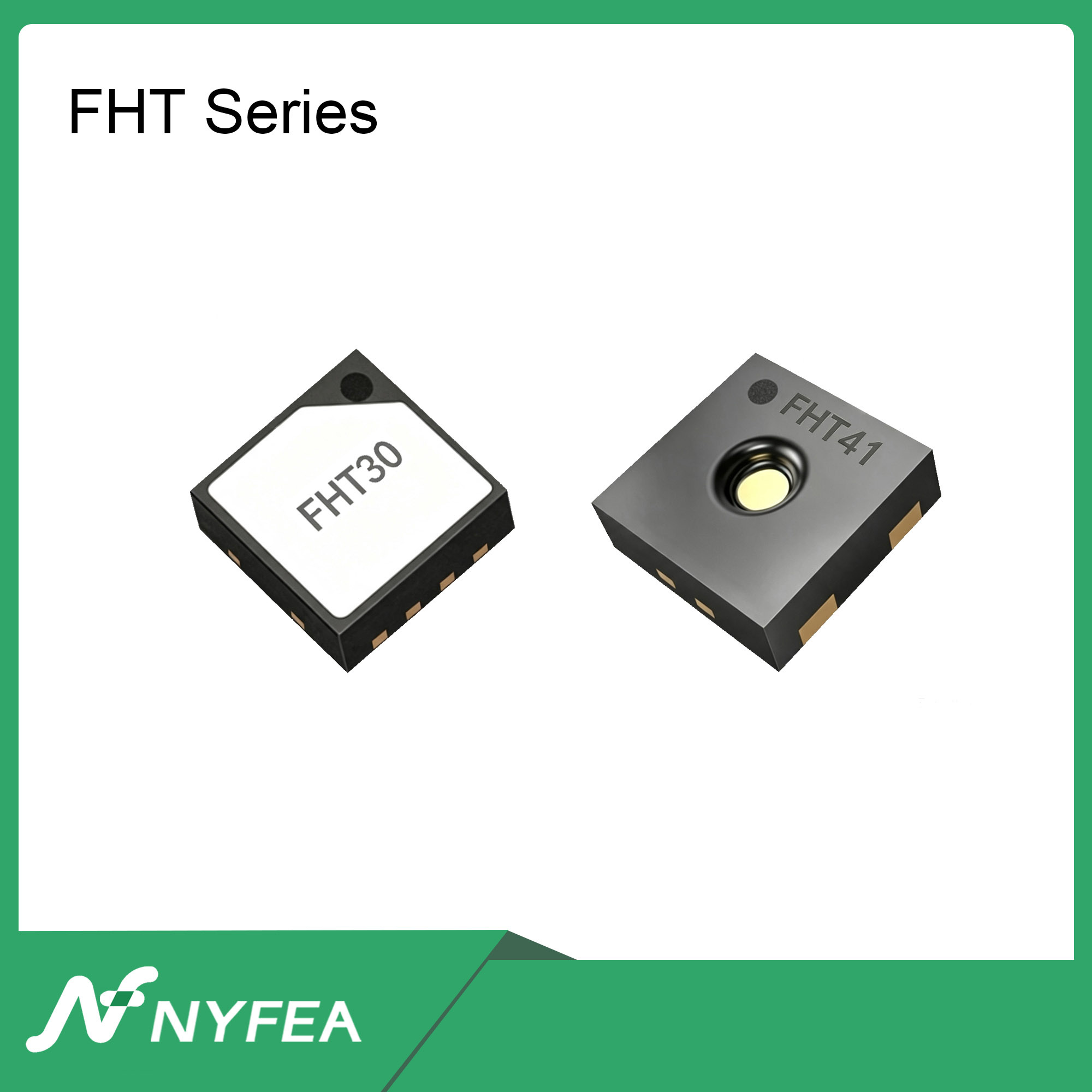
Carry the fan-control policy forward as an application requirement. For a new board, evaluate NYFEA FHT41 against the board’s supply, interface, package, measurement and environmental requirements. Verify the FHT41 driver and repeat the assembled-device checks for the chosen sensor.
Technical references
- Sensirion SHT4x datasheet · measurement command, conversion timing and CRC-protected response.
- Sensirion Design Guide for Humidity and Temperature Sensors · heat sources, airflow and sensor placement.
- STMicroelectronics STM32F4 HAL · time base, GPIO and I²C integration.
- NOAA National Weather Service on dew point and humidity · interpreting RH changes when temperature changes.