FHT SERIES · ENGINEERING SELECTION GUIDE
Temperature and Humidity Sensor Selection Guide for the NYFEA FHT Series
To choose a digital temperature and humidity sensor, first define the air you need to measure, the operating range and the allowable error. Then compare maximum-error limits, supply voltage, I²C behavior, package and average power under your intended settings. Finally, test the sensor in the finished enclosure: installation can change what the reading represents.
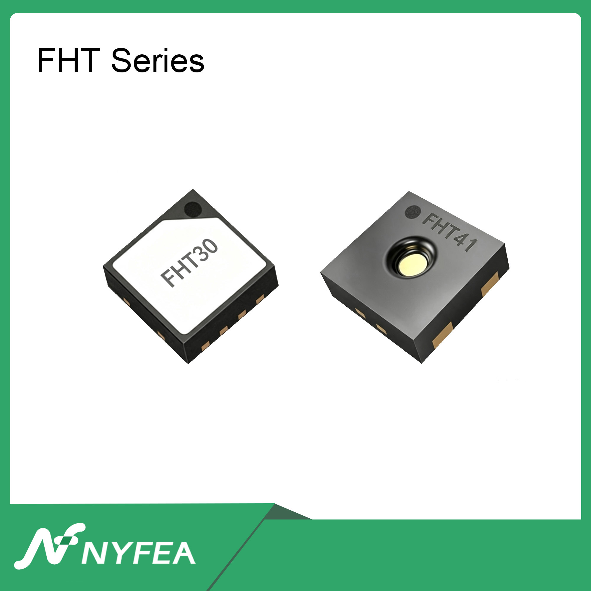
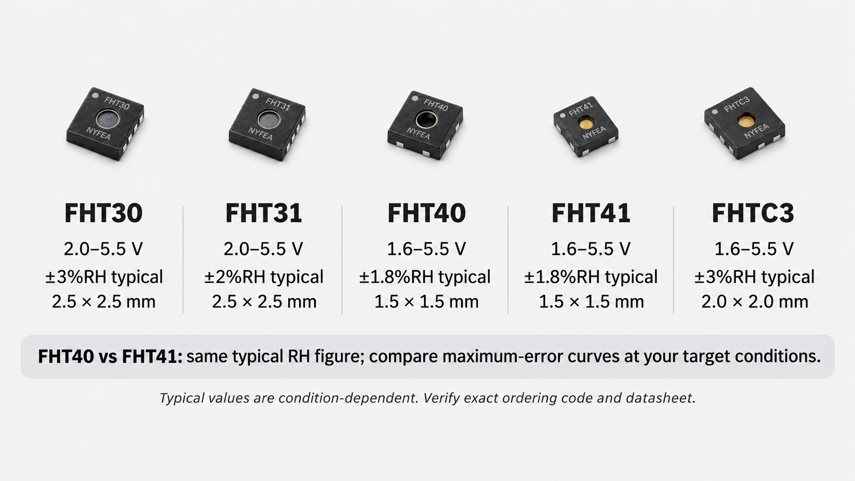
NYFEA’s FHT family includes digital temperature and relative-humidity sensors for room monitoring, wireless nodes, equipment cabinets and environmental control. This guide compares the documented characteristics of FHT30, FHT31, FHT40, FHT41 and FHTC3, then turns those specifications into a practical selection and verification process.
Abstract
This engineering guide uses NYFEA FHT specifications to connect component selection with finished-device performance. It explains how similar typical accuracy figures can conceal different maximum-error limits, why operating states matter for battery life, and how to distinguish sensor disagreement from installation effects. The comparison is documentation-based; the worked example is a selection calculation, not a laboratory result.
1. What does the sensor actually need to measure?
Start by naming the measurement location. A room monitor should represent room air. A sensor inside an equipment cabinet may instead need to represent air near a control board. Those are different tasks, even when both products display temperature and relative humidity.
This guide concerns sensor ICs for measuring air temperature and relative humidity. A digital interface simplifies connection to a microcontroller; it does not turn an exposed IC into a sealed probe for liquid immersion or direct measurement of a solid object's temperature.
| Requirement | Define it in practical terms |
|---|---|
| Measurement location | Room air, enclosure air, inlet air or another specified location |
| Operating conditions | Temperature and humidity range, including important transitions |
| Acceptable error | Allowable temperature and RH error at the conditions that matter |
| Required behavior | Update interval, settling time, fault response and power budget |
A wall-mounted display may prioritize stable room readings. A ventilation controller also needs useful response near its switching threshold. A battery logger must preserve measurement quality and operating life.
What decision will this reading support? That answer determines which specifications deserve attention.
2. Why can an accurate sensor report the wrong room humidity?
A humidity sensor measures the environment around its sensing area. It does not automatically measure conditions outside its enclosure.

Relative humidity is defined by:
Here, e is the water-vapor partial pressure and es(T) is the saturation vapor pressure at the same temperature.
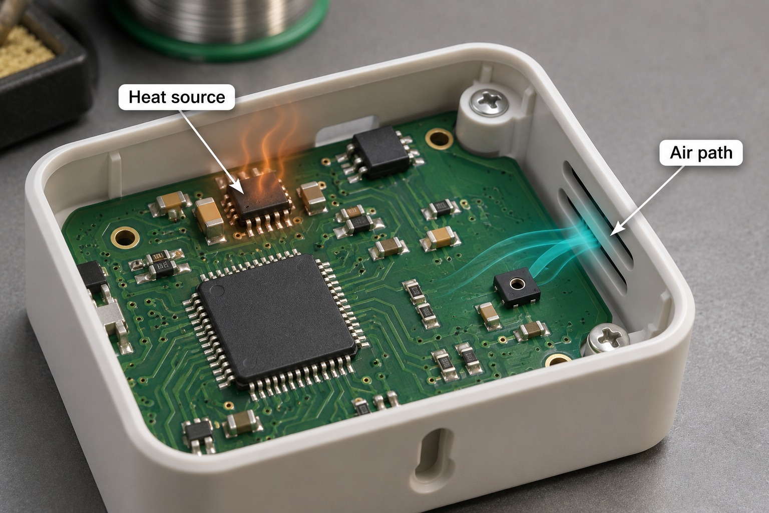
If local air becomes warmer while its water-vapor partial pressure remains unchanged, its relative humidity decreases. A sensor warmed by a regulator, processor or nearby copper can therefore report lower RH than a cooler reference elsewhere.
When humidity readings disagree, compare temperature and installation conditions before attributing the difference to sensor accuracy.
- Does the difference appear after the enclosure is closed?
- Do readings change with processor, radio or display activity?
- Does the sensing opening have a clear path to representative air?
- Have the sensor and reference had enough time to settle?
A tighter component specification cannot remove a temperature gradient created by the product itself.
3. How do the FHT sensor families compare?
The table provides an initial screening summary. These are typical headline accuracy figures, not maximum errors guaranteed throughout the complete measurement range.
| Sensor | Typical RH accuracy | Typical temperature accuracy | Supply | Measurement range | Package |
|---|---|---|---|---|---|
| FHT30 | ±3%RH | ±0.3°C | 2.0–5.5 V | 0–100%RH −45 to +130°C | DFN8 2.5 × 2.5 mm footprint |
| FHT31 | ±2%RH | ±0.2°C | 2.0–5.5 V | 0–100%RH −45 to +130°C | DFN8 |
| FHT40 | ±1.8%RH | ±0.2°C | 1.6–5.5 V | 0–100%RH −40 to +125°C | DFN4 1.5 × 1.5 mm footprint |
| FHT41 | ±1.8%RH | ±0.2°C | 1.6–5.5 V | 0–100%RH −40 to +125°C | DFN4 1.5 × 1.5 mm footprint |
| FHTC3 | ±3%RH | ±0.3°C | 1.6–5.5 V | 0–100%RH −45 to +130°C | DFN6 2 × 2 mm footprint |
Sources: FHT30, FHT40, FHT41 and FHTC3 datasheets. FHT31 headline figures are from NYFEA’s product overview; condition-specific limits require its corresponding datasheet. The FHTC3 temperature range follows its electrical-characteristics table. Technical basis.
Which FHT candidates should you evaluate first?
Use the requirement that would rule out a part first. These are starting points for evaluation, not unconditional product recommendations.
| Your design constraint | Candidates to examine | What decides the choice |
|---|---|---|
| A 1.8 V sensor supply | FHT40, FHT41 or FHTC3 | Their documented supply range includes 1.8 V. FHT30/FHT31 start at 2.0 V; also check logic levels and supply tolerance. |
| A compact 1.5 × 1.5 mm footprint | FHT40 or FHT41 | Compare error limits at the required conditions and verify the complete package drawing. |
| Selectable I²C address on the sensor | FHT30 | Its ADDR pin selects 0x44 or 0x45. Check the rest of the bus before assigning either address. |
| Battery operation with long gaps between readings | FHT40, FHT41 or FHTC3 | Compare full-cycle current at the required repeatability and sampling interval; implement the documented low-power states. |
| A tighter RH error allowance | Compare the relevant grades, including FHT41 | Use maximum-error curves, not only the shared ±1.8%RH typical figure. See the example below. |
Measurement range is not uniform accuracy
The measurement range describes where readings are provided. It does not mean the smallest stated error applies everywhere.
For example, FHT30 specifies typical temperature accuracy of ±0.3°C over −40 to +90°C. Its measurement range extends beyond that interval.
Record the complete ordering code
NYFEA’s overview lists FHT30-TR, FHT31-TR, FHT40-TR, FHT41-TR and FHTC3-TR as membrane-equipped versions, and FHT40-DD-TR without a membrane.
Confirm configuration and handling instructions. “With membrane” alone does not establish an IP rating, suitability for liquid exposure or a quantified response improvement.
4. Humidity sensor accuracy: what do typical and maximum values mean?
Typical accuracy and maximum-error limits answer different questions. Both documents state a typical RH accuracy of ±1.8%RH in the central humidity region. Their maximum-error curves differ.
Typical accuracy describes the manufacturer's stated typical performance under specified conditions. A maximum-error limit gives the published error boundary for its stated conditions. Resolution is the smallest reported step; extra decimal places do not prove smaller error. Repeatability describes the variation in repeated readings under unchanged conditions, rather than agreement with a reference.
For example, ±3%RH means three RH percentage points, not three percent of the displayed value. Relative to a reference of 50%RH, a difference of 3%RH corresponds to 47%RH or 53%RH. This explains the unit; it is not a calibration result.
FHT40 vs FHT41: the difference behind the same typical value
- FHT40 at 25°C: approximately ±3.5%RH maximum over 10–90%RH.
- FHT41 at 25°C: approximately ±2.5%RH maximum over 0–90%RH.
Source: FHT40 and FHT41 datasheets, page 6, humidity-accuracy plots at 25°C. Read other operating conditions from the corresponding tolerance information.
These are component specifications under stated conditions, not measurements of a finished product.
A worked screening example
Suppose a design uses ±3%RH at 25°C and 50%RH as its component-screening requirement.
| Candidate | Maximum at this condition | Screening result |
|---|---|---|
| FHT40 | Approximately ±3.5%RH | Does not meet this maximum-error criterion |
| FHT41 | Approximately ±2.5%RH | Meets this component-level criterion |
The conclusion is limited to the stated condition and criterion. It does not establish performance across every temperature or humidity condition.
If ±3%RH is the whole-device requirement, consider installation effects, reference uncertainty, drift and other relevant contributions. Do not assign the entire allowance to the sensor and assume the rest of the system contributes nothing.
5. What must be checked before connecting an FHT sensor to a microcontroller?
Sharing I²C does not establish identical addresses, commands or firmware behavior.
| Part or family | 7-bit address | Design implication |
|---|---|---|
| FHT30 | 0x44 or 0x45 | Check the ADDR-pin connection |
| FHT40-DD-TR | 0x44 | Check for an address conflict |
| FHT41-TR | 0x45 | Use the address for this order code |
| FHTC3 | 0x70 | Review wake, measurement and sleep sequences |
Do not extend an address specification to another ordering variant without checking its documentation.
- Power and logic levels. Check supply, I²C pull-up rail and controller input limits.
- Pin assignments and footprint. Match the exact package drawing and orientation.
- Communication sequence. Confirm commands, waits, response format and integrity checks.
- Operating states. Review sleep, reset, heater and recovery behavior.
- Bus conditions. Check rise time, loading and the selected clock rate.
A matching package or acknowledged address is useful evidence of progress. Neither proves the complete implementation is correct.
FHT30 package markings and typical application circuit
Package markings
F identifies NYFEA in the model name. The corner dot marks pin 1, and 24156 illustrates the year, week and product ID code.
Typical I²C application circuit
Place the 100 nF bypass capacitor close to VDD. SCL and SDA each have a pull-up to VDD. Check pull-up values and the ADDR, ALERT and nRESET connections in the FHT30 documentation.
6. How do you select a low-power temperature and humidity sensor?
Compare the intended operating sequence, not just the smallest current on the first page.
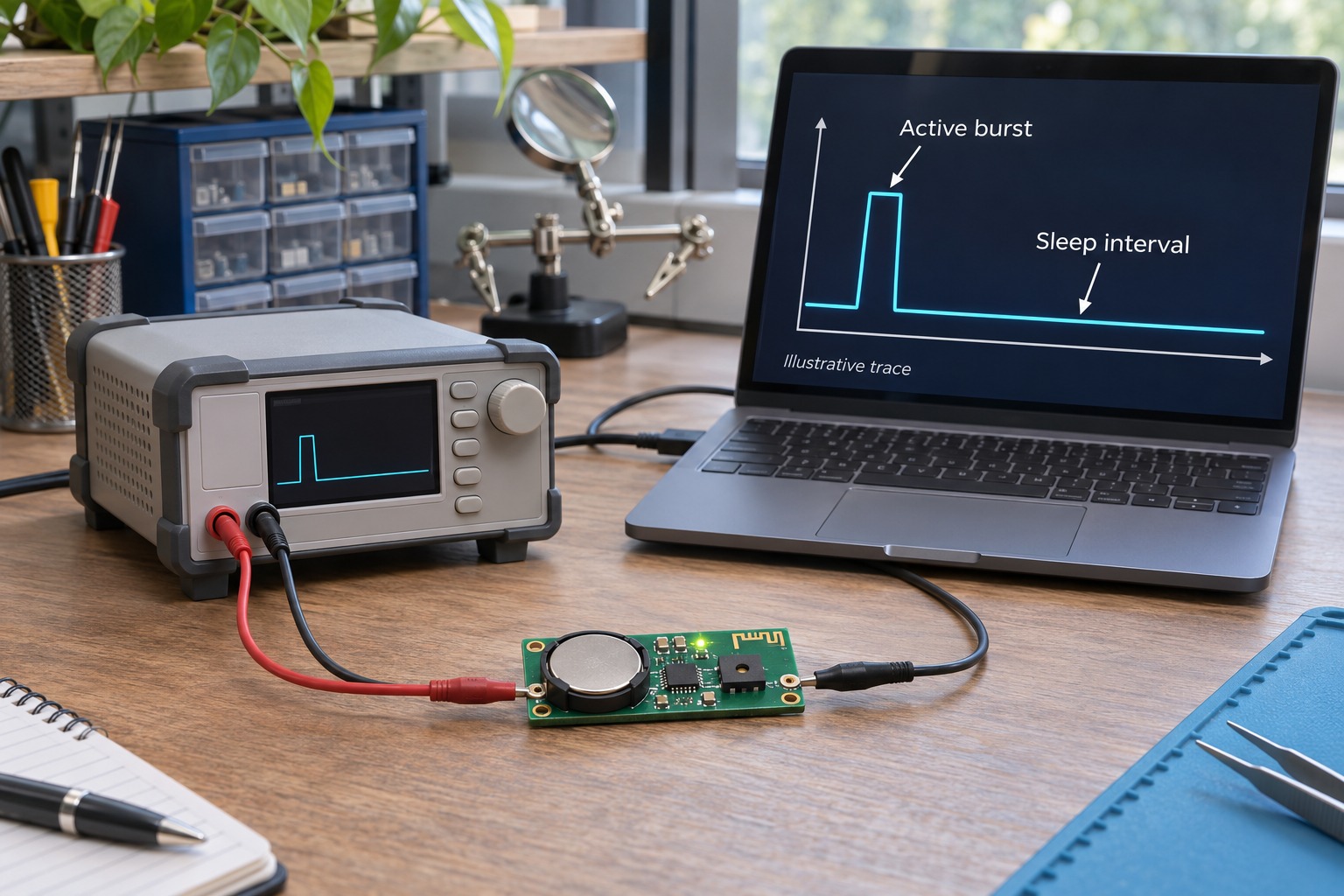
Include every state that occurs. For the finished product, also include the controller, regulator, communications and display.
Why sleep handling matters
The FHTC3 electrical table lists 0.2 µA typical sleep current and 45 µA typical idle current at 25°C and 3.3 V. These are different operating states, not two estimates for the same state. Its documentation requires an explicit sleep command. Source: FHTC3 datasheet, electrical characteristics, page 6.
Leaving FHTC3 idle between readings will not achieve sleep-state current simply because measurements are infrequent.
The approximately 0.4 µA typical average current associated with low-repeatability, 1 Hz operation of FHT40/FHT41 is not the current for every mode or a complete wireless node.
- Set the update interval from the application’s needs.
- Select measurement settings that provide adequate repeatability.
- Put the sensor and controller into their intended states between readings.
- Measure current across a complete cycle.
- Evaluate heater operation separately if used.
For constant-voltage operation, average power is approximately Pavg = V × Iavg. When comparing different supply voltages, use energy per cycle or average power rather than current alone. Account for regulator efficiency and the rest of the device before estimating battery life.
7. Which installation changes should come before upgrading the sensor?
Improve installation first when the observed error follows the product’s operating state or mechanical arrangement.
Separate the sensor from heat sources
Keep it away from regulators, processors, power components and active displays. Review heat conduction through the PCB as well as distance through air.
A sensor at the board edge can still be coupled to a hot area through copper.
Give ambient air a useful path
Avoid a stagnant enclosure pocket when the goal is to measure external air. Check the opening, internal air volume and barriers.
A fast sensor cannot make a poorly ventilated enclosure respond quickly.
Treat contamination and condensation as design conditions
Review residues, adhesives, coatings and chemical exposure. Keep materials away from the sensing area unless their suitability is established.
Follow the operating instructions for any integrated heater. Heater-on readings do not represent undisturbed ambient conditions. Allow appropriate recovery before interpreting subsequent measurements.
The objective is to make conditions at the sensor represent the environment your product claims to measure.
Decide whether to change the part or the installation
- Error follows radio or display activity: log those events alongside temperature and RH, then repeat with that load disabled. Investigate heat paths if the difference changes with the load.
- Response becomes slow only inside the enclosure: repeat the same environmental transition with the cover open and closed. Review ventilation before selecting a faster sensor.
- Difference follows one sensor when positions are exchanged: compare that sensor against a suitable reference. This observation identifies a next check; it does not establish which sensor is correct.
8. How can a candidate sensor be validated in the finished device?
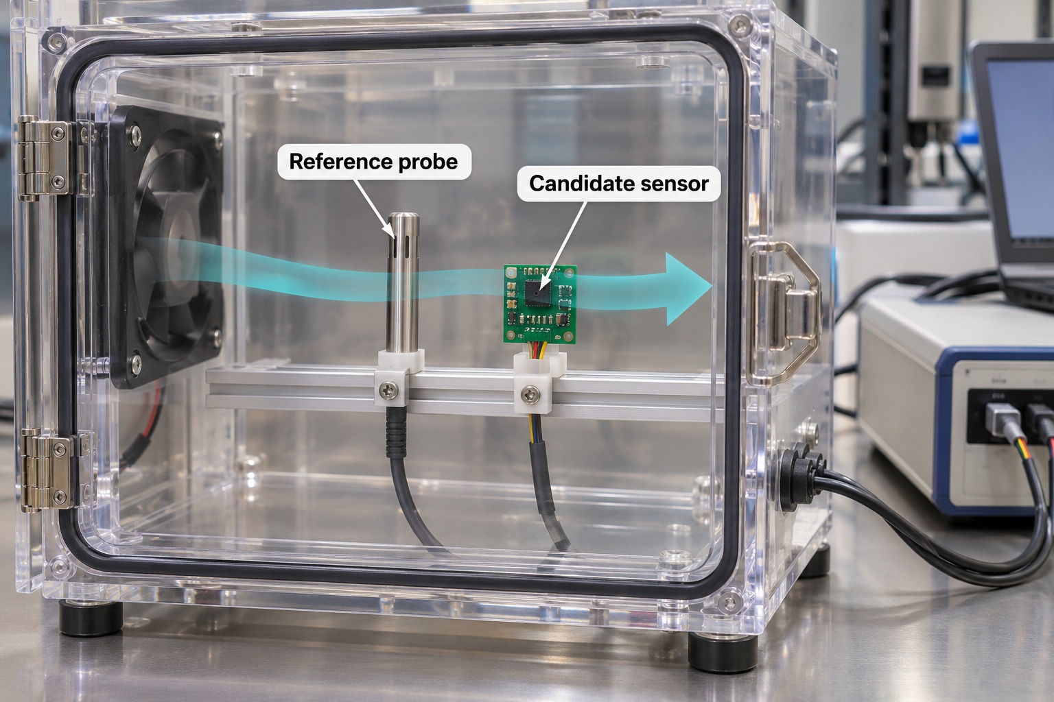
Use a comparison that distinguishes sensor behavior from installation effects.
Define acceptance before measuring
Record temperature/RH conditions, allowable error, update interval and settling requirements. Identify whether steady-state agreement, response to change or both matter.
Select a suitable reference
Check uncertainty, calibration status and stability. A reference that cannot resolve the decision cannot establish a small performance advantage.
Compare in a shared environment
Use comparable airflow without letting the reference or fixture obstruct the candidate. Start with a steady condition, then cover the temperature/RH points and transitions important to the application.
Log timestamps, reference temperature/RH, candidate temperature/RH and operating events. Define a settling criterion before the run; one pair of readings is not an accuracy evaluation.
Repeat in the assembled product
Repeat with the same reference arrangement and firmware settings, first in the initial setup and then in the final enclosure. Exercise relevant loads, including radio, display or controller.
If the difference appears only after assembly, investigate installation before applying an offset or changing sensor grade.
Test behavior around the measurement
Verify communication failures, restart and recovery. For controllers, check how stale or missing readings affect the output.
ΔRH = RHcandidate − RHreference
Report ΔT in °C and ΔRH in RH percentage points. Compare settled results and response behavior against the predeclared limits, while accounting for reference uncertainty. A fixed software offset should not be used to conceal an error that changes with temperature, enclosure state or electrical load.
| Record | Why it matters |
|---|---|
| Ordering code and firmware settings | Makes the result reproducible |
| Reference and environmental conditions | Defines what the comparison can establish |
| PCB, enclosure and operating loads | Reveals integration effects |
| Timestamped temperature and RH | Supports aligned comparison and settling analysis |
| Acceptance rule and result | Connects evidence to the decision |
Apply a decision rule that accounts for uncertainty. A displayed difference equal to the acceptance limit is not sufficient evidence of compliance.
Frequently asked questions
How do I choose a temperature and humidity sensor?
Define measurement location, operating range and allowable error first. Screen for electrical and mechanical compatibility, then compare condition-specific accuracy, operating-state power and response. Validate the sensor in the final PCB and enclosure before making a finished-product accuracy claim.
Does ±1.8%RH mean the same accuracy across the full humidity range?
No. A typical value applies under specified conditions. Check humidity and temperature tolerance curves, including maximum limits where provided. Measurement range and the interval over which a particular accuracy applies are different specifications.
Can I use the same I²C driver for every FHT sensor?
Do not assume so. FHT devices can differ in address, commands, timing and power-state handling. Check the exact ordering code and test response parsing, integrity checks and recovery before reusing a driver.
Does a membrane-equipped sensor make the product waterproof?
No. Confirm the membrane specification, assembly instructions and intended exposure conditions. Enclosure sealing and environmental protection require their own evaluation.
Why does the reading change after I close the enclosure?
Closure can change airflow, settling time and heat transfer. Compare temperature and RH before and after closure while keeping the external environment stable. A repeatable change associated with closure points to an installation effect to investigate.
Is the lowest sleep current the best indicator of battery life?
No. Battery life depends on time spent measuring, idle, sleeping and communicating, as well as the rest of the electronics. Compare complete cycles using the intended firmware rather than sleep current alone.
What is the difference between humidity sensor accuracy and resolution?
Accuracy concerns how closely a reading represents the measured quantity under stated conditions. Resolution is the smallest reported increment. A display showing 50.01%RH does not establish ±0.01%RH accuracy. Compare the sensor's published error limits with your requirement, and use resolution only to assess the granularity of the output.
Can a humidity sensor use 5 V power with a 3.3 V microcontroller?
Check supply and signal voltages separately. A sensor's permitted 5 V supply does not prove the microcontroller can tolerate SDA and SCL pulled up to 5 V. Verify the input thresholds and absolute maximum ratings of both devices, then use a compatible pull-up rail or suitable level translation where required.
Conclusion
A useful selection process connects the measurement task, documented component limits, operating sequence and final installation.
Keep a shortlist with the exact order code, the operating conditions it covers and the unresolved checks. Approve a candidate only after the relevant electrical, measurement and recovery tests pass the agreed criteria. That record turns a plausible specification match into a reviewable engineering decision.
Technical basis
This analysis uses the FHT30, FHT40, FHT41 and FHTC3 datasheets and the NYFEA product-family overview. FHT31 headline values and membrane classifications come from the overview. The worked comparison is a conditional selection example, not a laboratory measurement or production qualification.
- FHT30 technical information — accuracy conditions, interface and electrical characteristics.
- FHT40 technical information — humidity error limits and documented ordering variant.
- FHT41 technical information — humidity error limits and documented address.
- FHT series specifications — model and document selection.
Evaluate an FHT sensor for your design
Send NYFEA your supply voltage, temperature/RH range, allowable error, sampling interval and enclosure sketch. Use these requirements to request the relevant FHT datasheets and discuss candidates for sample evaluation.