CLRC663 LPCD I/Q 0x00 on STM32: Register Debug Guide
A case analysis of a published STM32 and CLRC66303 debugging problem: normal UID reading works, LPCD I/Q remains at 0x00, and the Error register changes to 0x80 after LoadReg.
QUICK ANSWER
If CLRC66303 LPCD I/Q remains at 0x00, do not tune the thresholds first. Confirm Version 0x1A, inspect Error 0x80, verify all four LoadReg FIFO parameters, wait for command completion, and then repeat LPCD calibration on the assembled reader.
Scope and Evidence Boundaries
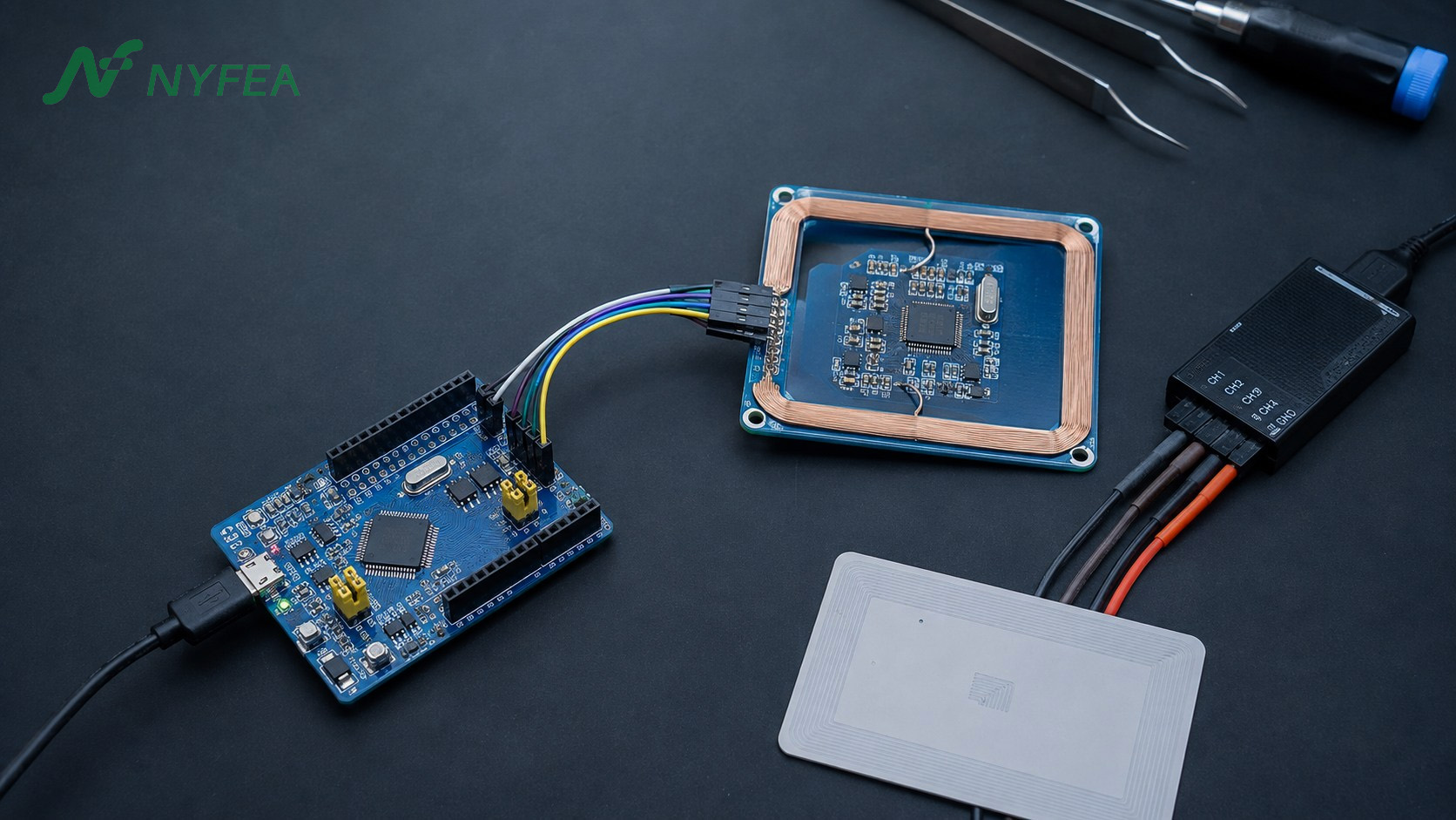
The STM32, custom CLRC663 PCB, version value, I/Q values and Error-register transition come from a public NXP Community discussion.
Command parameters, revision handling and SPI sequencing are checked against NXP’s current data sheet and application notes.
The public thread does not provide a confirmed root cause, corrected I/Q values or before-and-after read-range data.
The Published STM32 and CLRC66303 Community Case
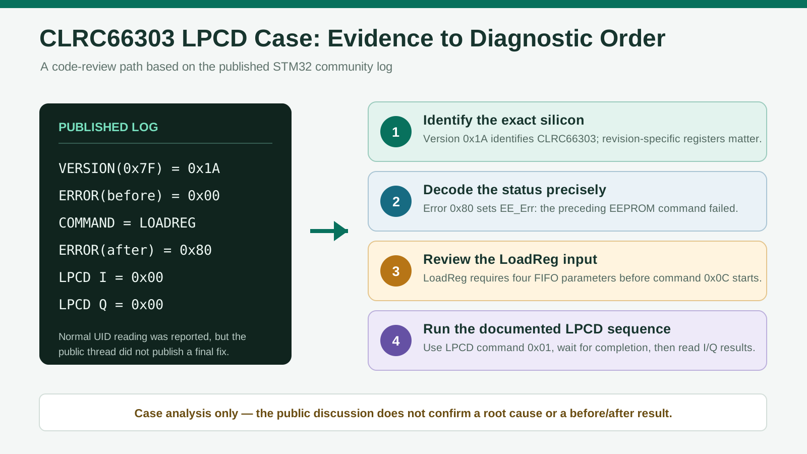
An engineer reported a custom CLRC663 PCB controlled by an STM32. Normal card operation could read a UID, but the LPCD example returned in-phase and quadrature values of 0x00. The Error register was clear before LoadReg and changed to 0x80 after the command. The complete discussion is available in the NXP Community STM32/LPCD thread.
VERSION(0x7F) = 0x1A
ERROR(before)  = 0x00
COMMAND        = LOADREG
ERROR(after)   = 0x80
LPCD I         = 0x00
LPCD Q         = 0x00
Swipe to view all columns →
| Published fact | Engineering significance |
|---|---|
| Custom PCB and STM32 host | The issue must be separated across host communication, command handling, RF state and antenna behavior. |
| Normal UID reading was reported | Part of the host and active card-reading path operates; this does not validate EEPROM commands or LPCD. |
VERSION=0x1A | The register map and firmware path should be selected for CLRC66303. |
ERROR=0x80 after LoadReg | The preceding EEPROM command failed; the value alone does not prove physical EEPROM damage. |
LPCD I/Q both equal 0x00 | No useful measurement was captured, so threshold tuning should not be the first action. |
What the Register Log Actually Proves
Version 0x1A identifies CLRC66303
According to the CLRC663 product data sheet, Version 0x1A identifies CLRC66303. Select revision-matched register definitions before loading protocol or LPCD configuration.
Error 0x80 is an EEPROM-command error—not proof of a damaged IC
In the Error register definition, bit 7 is EE_Err: the preceding EEPROM command failed. Check its parameters, address ranges, FIFO contents, command order and completion handling; this bit alone does not prove physical EEPROM damage.
A working UID read does not validate LPCD
Normal card reading uses an active RF protocol exchange; LPCD uses low-power sampling to detect changes in antenna response. A successful UID read therefore does not validate LPCD command completion or its result registers.
Two Code-Level Checks Worth Making First
1. Confirm the four LoadReg parameters in FIFO
The documented LoadReg command is 0x0C. Before it starts, FIFO must contain four parameters: EEPROM address high, EEPROM address low, destination register address and register count.
The published snippet starts LoadReg without showing these bytes. They may exist elsewhere in the application, so this is a diagnostic lead—not a confirmed root cause.
set_reader_idle();
flush_fifo();

write_fifo(eeprom_address_high);
write_fifo(eeprom_address_low);
write_fifo(destination_register);
write_fifo(register_count);

write_command(LOADREG);       // documented command: 0x0C
wait_for_command_completion();
    read_error_register();
LoadProtocol vs. LoadReg
NXP AN11022 distinguishes the two operations: LoadProtocol applies a built-in protocol profile, while LoadReg copies a user-defined EEPROM block into registers. Verify that the firmware is using the command intended for its configuration source.
2. Do not treat 0x37 as a hidden LPCD calibration command
In the current CLRC663 register map, the LPCD command is 0x01; address 0x37 is RxThreshold, not an LPCD command. Do not use undocumented Command values in a production driver.
Why the silicon revision changes the register review
CLRC66303 adds LPCD_OPTIONS at 0x3A, a location reserved in earlier variants. Use the full device identity and matching data-sheet revision instead of a universal CLRC663 register list.
How to Debug CLRC663 Register Settings Safely
The fastest path is to change one layer at a time. Do not retune the antenna, rewrite the protocol profile and alter LPCD thresholds in the same test.
- Lock the device identity. Record the full order code, top marking, version value, board revision, firmware commit and data-sheet revision.
- Prove SPI transactions. Verify repeated register readback, address framing, clock mode and NSS timing with a logic analyzer. NXP AN12657 requires NSS to return high between separate SPI commands.
- Return to a known state. Set the reader idle, stop pending operations, flush FIFO and clear the relevant interrupt status before a new command sequence.
- Run LoadReg with documented inputs. Write all four FIFO parameters, start command
0x0C, wait for completion and then record the Error register. - Run the documented LPCD flow. Apply revision-appropriate RF, timer and LPCD settings, use the documented LPCD command and wait for the expected completion or wake event.
- Capture repeatable evidence. Log no-card and card-present I/Q results, interrupt status, error status, elapsed time and physical test conditions.
EE_Err set, stop and correct the EEPROM command path before changing LPCD thresholds. A threshold cannot repair a command that never produced a valid measurement.
Why Antenna and Final-Enclosure Evidence Still Matters
The developer reported that the antenna had been tuned. NXP support nevertheless requested the antenna Smith chart and schematic before giving hardware-specific guidance. That is appropriate: a normal UID read does not establish that short LPCD sampling produces a useful and repeatable I/Q separation.
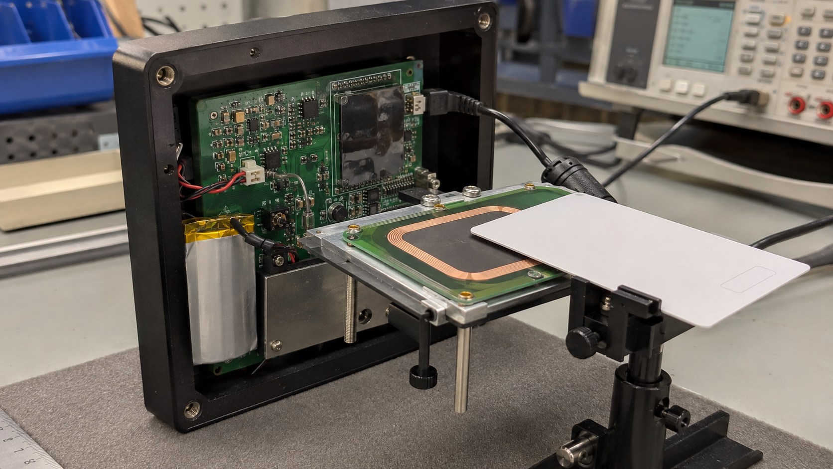
Batteries, ferrite, metal, displays, cables and coatings can change antenna loss, resonance and field distribution. Repeat LPCD calibration in the complete assembly, then use the separate CLRC663 antenna design and read-range guide for matching evidence.
Swipe to view all columns →
| Test mode | What it verifies | Evidence to retain |
|---|---|---|
| Normal card communication | A complete protocol transaction under an active RF field | Card identity, distance, orientation, attempts, success rate and timing |
| LPCD with no card | The environmental I/Q baseline and false-wake behavior | I/Q samples, temperature, enclosure state, wake count and average current |
| LPCD with a target card | Whether the card produces a repeatable change at the required position | Card type, position, loaded I/Q values, missed events and wake latency |
Build a Verification Record
The public case has no published closure, so record explicit pass criteria and report results only after measuring the actual board.
Swipe to view all columns →
| Checkpoint | Required evidence | Valid release statement |
|---|---|---|
| Host interface | Logic-analyzer capture and repeated register readback | SPI framing and NSS timing passed the defined test. |
| LoadReg | Four FIFO parameters, completion event and Error status | The selected EEPROM block loaded without a reported command error. |
| LPCD measurement | Repeatable no-card and card-present I/Q samples | The board produced a measurable separation under the stated conditions. |
| Final assembly | Smith chart, schematic, enclosure stack and card matrix | The assembled reader met the project-specific wake and communication criteria. |
| Extended operation | Missed detections, false wakes, current and recovery logs | The tested samples passed the defined duration and environmental boundaries. |
Applying the Same Validation Method to NYFEA NF663
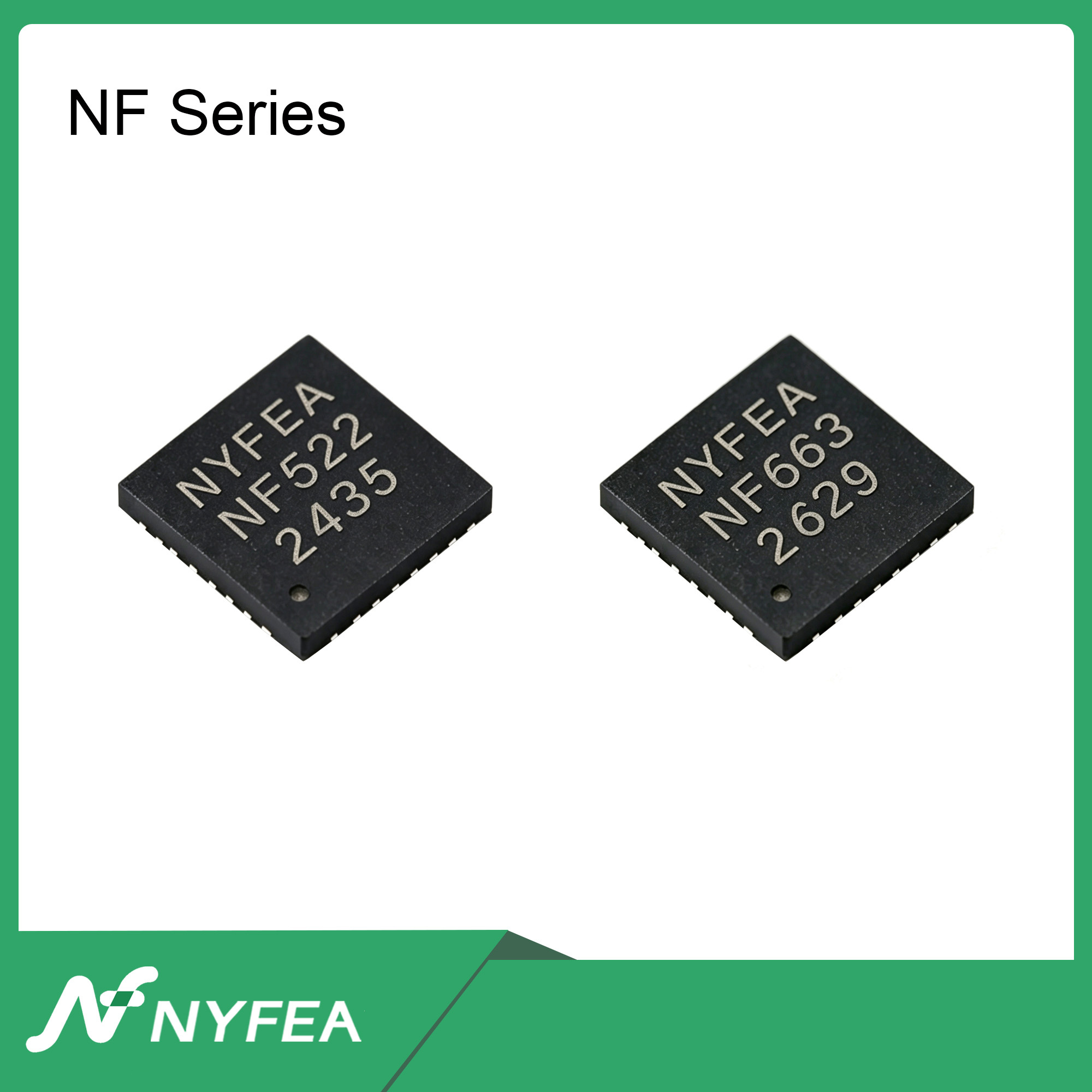
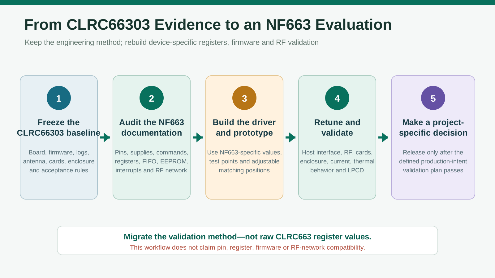
The same validation plan—host-interface readback, documented commands, loaded and unloaded LPCD calibration, antenna measurement and final-enclosure testing—can be applied when assessing the NYFEA NF663.
NF663 is a multi-protocol 13.56 MHz reader frontend with a 512-byte FIFO, 8 kB EEPROM, SPI, I²C/I²CL, UART and low-power card detection. This functional overlap supports the same test method—not pin, command, register or RF-network compatibility. Build the driver from the NF663 specification and revalidate it on dedicated hardware.
Conclusion
For LPCD I/Q stuck at 0x00, identify the silicon, verify SPI, validate LoadReg inputs and completion, run the documented LPCD flow, and qualify the antenna in the final enclosure. Apply the same evidence-based workflow—not raw register values—when evaluating NF663.
Frequently Asked Questions
Why does CLRC663 LPCD I/Q stay at 0x00?
An I/Q result of 0x00 can indicate that no valid LPCD measurement was completed or captured. Verify the device revision, prior command errors, documented LPCD sequence, completion event and RF measurement state before changing thresholds.
What does CLRC663 Error 0x80 mean after LoadReg?
Error 0x80 sets EE_Err, meaning an error occurred during the preceding EEPROM command. It does not alone prove EEPROM damage. Check the four LoadReg FIFO parameters, valid address ranges, command order and completion handling.
What device does CLRC663 Version 0x1A identify?
Version-register value 0x1A identifies CLRC66303. Use the CLRC66303 register definitions and revision-appropriate LPCD configuration rather than a generic family-level script.
Is 0x37 a CLRC663 LPCD calibration command?
No. In the current CLRC663 register map, 0x37 is the RxThreshold register address. The documented LPCD command value is 0x01; undocumented command values should not be used in a production driver.
Why can normal card reading work while LPCD fails?
Normal reading performs an active RF protocol exchange, while LPCD uses a low-power sampling and threshold process. A successful UID read does not validate EEPROM loading, LPCD timing, I/Q measurement or false-wake performance.
Why does LPCD behavior change after enclosure assembly?
Metal, batteries, ferrite, displays, ground planes and physical spacing can alter the antenna response. Recalibrate the no-card baseline and verify loaded I/Q separation, missed detections and false wakes in the complete product.
Can CLRC663 register settings be copied to NF663?
No. Reuse the diagnostic and validation method, not raw register addresses or values. Build the NF663 driver from its own product specification and revalidate the host interface, antenna, LPCD behavior and final system.
Primary Engineering Sources
- NXP — CLRC663 and CLRC663 plus Product Data Sheet, Rev. 5.4
- NXP AN12657 — Using the CLRC663 Family Host Interfaces
- NXP AN11145 — CLRC663 Low-Power Card Detection
- NXP Community — STM32 custom-board LPCD I/Q 0x00 discussion
- NXP Community — CLRC663 plus LPCD Tip & Tricks
- NYFEA — NF663 Multi-Protocol 13.56 MHz RFID Reader IC
NEXT ENGINEERING STEP
Review the NF663 Data Before Building the Prototype
Define the host interface, card set, antenna, enclosure and acceptance criteria first. NYFEA can support an NF663 document review and production-intent prototype evaluation without assuming direct CLRC663 compatibility.