ENGINEERING IMPLEMENTATION GUIDE
ESP32 and SHT40 Smart Greenhouse: Wiring, Heater Control and Fault-Safe Code
A greenhouse controller needs more than a readable SHT40 value. This guide connects the sensor to an ESP32, keeps heated or mist-affected readings out of the control loop, and shows how to test fan and spray behavior before connecting live loads.
What must work before an SHT40 controls a greenhouse?
First obtain a valid SHT40 measurement on a verified 3.3 V I²C bus. Place the sensor where it samples crop-zone air without direct sun or spray. Then add fan hysteresis and a separate irrigation trigger. During a heater pulse, spraying, and the subsequent settling period, do not feed affected temperature or relative-humidity values to the controller. Test fault behavior with the loads disconnected before commissioning the actual fan, pump or valve.
Sensor Capabilities and Application Limits
Key SHT40 Specifications
| Parameter | Typical Value or Range | Engineering Implications |
|---|---|---|
| Relative humidity accuracy | ±1.8 %RH | Suitable for greenhouse trend monitoring and most environmental controls |
| Relative humidity range | 0–100 %RH | Covers high-humidity conditions before and after condensation; persistent condensation still requires protection |
| Temperature accuracy | ±0.2 °C | Suitable for ventilation control and environmental logging; not a replacement for metrological calibration |
| Temperature range | −40 to 125 °C | The sensor measurement range does not define the rated operating range of every housing or module |
| Interface | I²C; default address 0x44 | Avoid address conflicts on a shared bus |
| Sensor supply voltage | 1.08–3.6 V | Bare sensors and unregulated modules must not be connected directly to 5 V |
| Integrated heater | Three power levels; two durations | For condensation removal and recovery from contamination; not for heating the greenhouse air |
The accuracy curves in the datasheet depend on environmental conditions. Near the extremes of the temperature and humidity ranges, maximum errors are generally higher than in the primary operating region.
Include hysteresis when defining control thresholds, and do not interpret small changes in a single measurement as definitive environmental changes.
Selecting Within the SHT4x Family
| Device | Typical RH Accuracy | Typical Temperature Accuracy | Recommended Applications |
|---|---|---|---|
| SHT40 | ±1.8 %RH | ±0.2 °C | Standard greenhouses, equipment rooms, warehouses, and consumer products |
| SHT41 | ±1.8 %RH | ±0.2 °C | Applications requiring better performance across the complete measurement range |
| SHT45 | ±1.0 %RH | ±0.1 °C | High-accuracy logging, instruments, and systems with more demanding calibration requirements |
Check the complete orderable part number. The current SHT4x datasheet describes a polyimide-membrane option and a removable protective-cover option.
Select protection against the actual spray, dust and chemical exposure, then verify response time and service access in the final installation. Do not assume every breakout board carries the same protection.
System Architecture and Hardware Wiring
Control-System Boundaries
Greenhouse systems should separate sensing, decision-making, and actuation.
The SHT40 measures ambient temperature and relative humidity; the ESP32 validates the data and executes threshold logic and the state machine; relays or drivers only switch the loads.
Spray-pump operation must have an independent trigger, preferably soil moisture content, an irrigation schedule, or a manual command.
| Layer | Primary Responsibility | Response to Failure |
|---|---|---|
| Sensing | Measure ambient temperature and RH; report communication status | Flag measurements as invalid; do not generate control inputs |
| Control | Filtering, hysteresis, state machine, interlocks, logging | Enter safe mode and retain the fault code |
| Actuation | Drive fans, pumps, solenoid valves, and alarms | Default to off on loss of power, or follow a documented risk assessment |
| Communications | Upload telemetry; receive remote commands | Loss of network connectivity must not compromise local safety control |
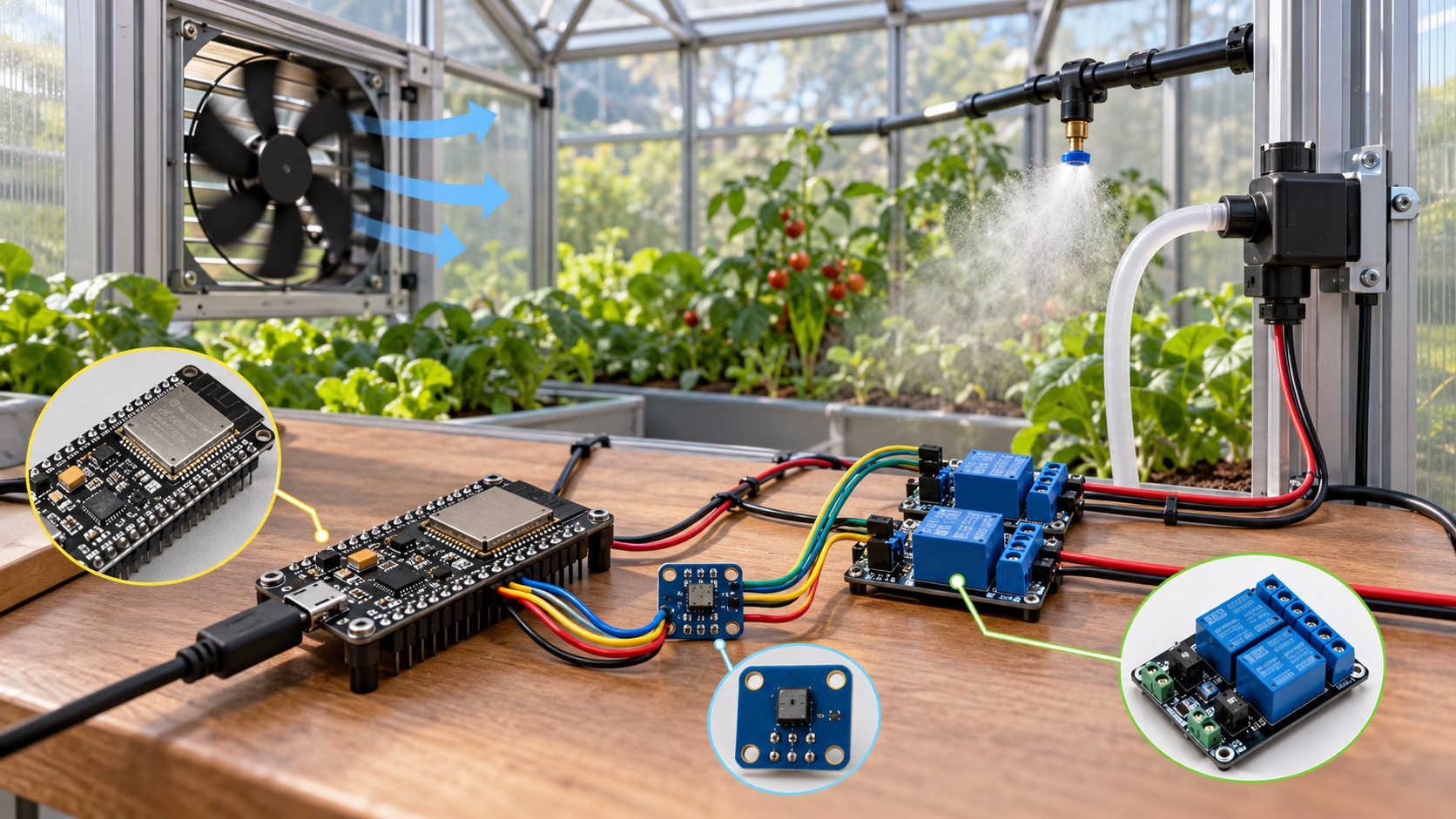
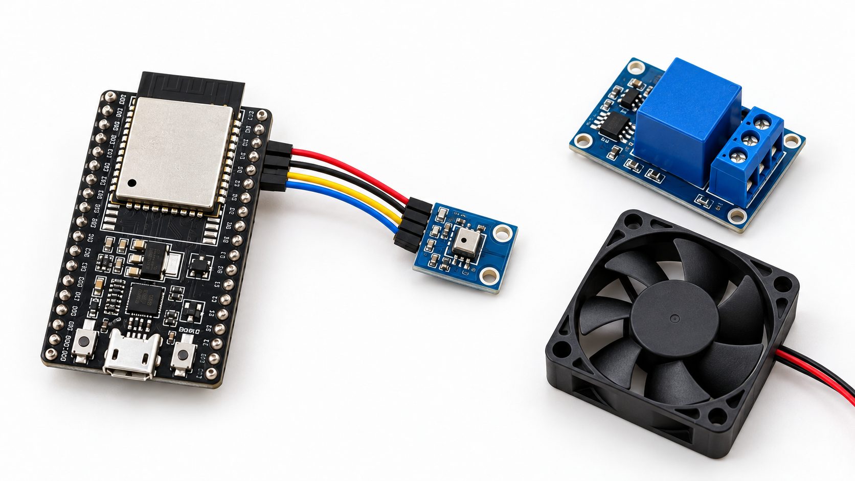
The diagram-like photo above is not a wiring schematic. The table below is the electrical connection reference for the low-voltage sensor path; the relay module and loads require their own reviewed schematics.
ESP32-to-SHT40 Wiring
| SHT40 Pin | ESP32 Pin | Notes |
|---|---|---|
| VDD or 3V3 | 3V3 | Supply a bare sensor or standard module from 3.3 V |
| GND | GND | Connect sensor and ESP32 grounds together |
| SDA | GPIO21 | Common default ESP32 SDA pin; configurable in firmware |
| SCL | GPIO22 | Common default ESP32 SCL pin; configurable in firmware |
Before using a third-party SHT40 breakout board, review its schematic. A board incorporating a voltage regulator and bidirectional level shifter may accept 5 V on VIN. If it contains only the sensor and pull-up resistors, use 3.3 V.
Do not infer the voltage rating from the connector silkscreen alone.
I²C Bus Wiring
Verify the low-voltage bus before connecting any actuator. These four checks prevent an address scan from being mistaken for a reliable measurement.
Pull-ups
Pull SDA and SCL up to 3.3 V. Many breakouts include resistors; account for their combined effective resistance when boards share the bus.
Bus length
There is no universal safe greenhouse cable length. Check total capacitance, pull-up values and noise at the installed clock rate. Put the acquisition node near the sensor or validate a suitable extender for longer runs.
Cable routing
Keep sensor wiring away from pump, fan, valve and AC power cables. Where paths cross, use near-perpendicular crossings and physical separation.
Clock and errors
In a noisy installation, start at 100 kHz. Record communication errors before changing speed or wiring.
Relay and Load Safety
An ESP32 GPIO cannot drive a relay coil, pump or fan directly. Select a driver for the actual load and 3.3 V input logic. Check its schematic: an optocoupler or removed jumper alone does not prove galvanic isolation or eliminate the need for a shared ground.
Suppress switching spikes
Protect DC coils and motors against flyback. For AC inductive loads, qualified personnel should select the appropriate snubber, surge protection, contactor or solid-state relay.
Keep power stable
Where practical, supply the ESP32 and relay coils from separate regulated branches. Add local decoupling and adequate bulk capacitance at the ESP32 input.
Enclose mains wiring
Use a compliant enclosure, overcurrent protection, protective grounding, guarded terminals and strain relief. Isolate power and verify it is absent before maintenance.
Check startup pins
Avoid boot-strapping pins for loads that could start unexpectedly. The reference sketch uses GPIO25 and GPIO26; confirm both are free on the selected board.
Greenhouse Installation and Environmental Protection
Sensor Placement
Sample crop-zone air
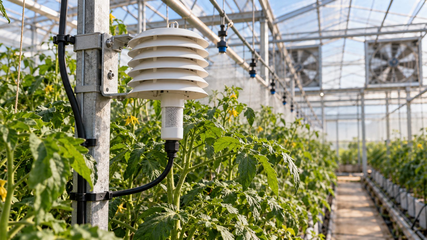
Mount the sensor near the canopy with airflow around it, clear of leaves, soil and dripping water.
Shade the sensor
Use a naturally ventilated radiation shield. Direct sun can bias temperature high and relative humidity low.
Avoid local extremes
Keep it away from fan outlets, heating pipes, cooling pads and spray nozzles. Use more than one node if the greenhouse has distinct microclimates.
Route condensate away
Use a drip loop and suitable cable entry so water cannot track along the cable into the enclosure.
Breathable Water-Repellent Protection and Maintenance
A breathable, water-repellent barrier can reduce direct droplet and dust exposure, but it does not make an entire sensor assembly waterproof.
Specify the barrier and housing separately, keep an air path to the opening, provide drainage and inspection access, and validate the response time.
Keep detergents, solvents, uncured adhesives and direct compressed air away from the sensing opening.
Integrated Heater and Measurement Validity
Correct Heater Invocation Sequence
In the Adafruit SHT4x library, setHeater() stores the mode for the next read. getEvent() sends the matching measurement or heater command and waits for its response.
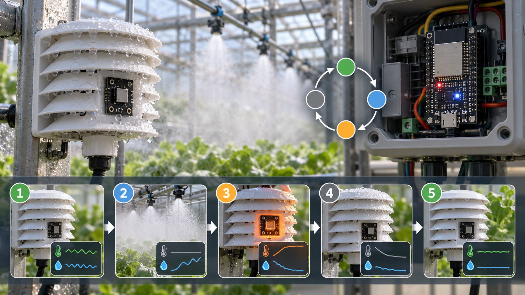
Select one heater mode, call getEvent() once, restore SHT4X_NO_HEATER, and wait for the installed sensor to settle before normal control resumes. The heated reading confirms a transaction, not ambient greenhouse conditions.
sht4.setHeater(SHT4X_MED_HEATER_1S);
sensors_event_t heaterHumidity, heaterTemperature;
bool heaterOk = sht4.getEvent(&heaterHumidity, &heaterTemperature);
sht4.setHeater(SHT4X_NO_HEATER);

// heaterHumidity and heaterTemperature are affected by sensor self-heating
// Do not use these values as inputs to fan, cooling-pad, or alarm control
cooldownStart = millis();
state = COOLING_DOWN;
Six Heater Operating Modes
| Library Constant | Nominal Power | Duration | Application Guidance |
|---|---|---|---|
| SHT4X_HIGH_HEATER_1S | High | 1 s | Recovery after significant condensation; use cautiously following validation |
| SHT4X_HIGH_HEATER_100MS | High | 0.1 s | Short, high-power heating pulse |
| SHT4X_MED_HEATER_1S | Medium | 1 s | Periodic recovery in high-humidity environments |
| SHT4X_MED_HEATER_100MS | Medium | 0.1 s | Less aggressive maintenance pulse |
| SHT4X_LOW_HEATER_1S | Low | 1 s | Power-constrained systems or small enclosures |
| SHT4X_LOW_HEATER_100MS | Low | 0.1 s | Short pulse with minimum disturbance |
The datasheet defines three heater power settings and two pulse durations. Do not derive an automatic heater schedule from one relative-humidity threshold alone: require sustained conditions, a minimum interval and a spray interlock.
Cooldown depends on the installed sensor and airflow. Persistent liquid exposure calls for a placement or protection change, not repeated heater pulses.
Recommended State Machine
| State | Permitted Actions | Prohibited Actions | Exit Condition |
|---|---|---|---|
| Normal Sampling | Update valid temperature/RH data and apply ventilation hysteresis | Repeated heater activation without spacing | Sustained high humidity and minimum heater interval reached |
| Spraying | Continue spray timer; suspend measurements susceptible to mist | Heater activation or use of mist-contaminated readings | Spray cycle complete |
| Heated Measurement | Execute a single heated getEvent() call | Feed that measurement into the controller | Command completes or reports an error |
| Cooldown | Temporarily retain the last valid measurement | Update control readings | Cooldown duration elapsed |
| Sensor Fault | Disable spraying and enter the predefined fail-safe state | Continue using stale measurements indefinitely | Reinitialization and consecutive valid samples |
ESP32 Reference Firmware
The complete sketch below is an ESP32 Arduino reference for a normally closed-loop greenhouse prototype: it samples the SHT40, applies fan hysteresis, accepts an S command for a single bench-test spray cycle, blocks control updates during heater and cooldown, and enters a fault state after repeated read failures.
The heater read can block the loop for approximately one second in the chosen mode, so this is a timed state machine rather than a fully non-blocking implementation. Disconnect live loads while validating the example.
#include <Wire.h>
#include <Adafruit_SHT4x.h>

constexpr uint8_t PIN_SDA = 21;
constexpr uint8_t PIN_SCL = 22;
constexpr uint8_t PIN_FAN = 25;
constexpr uint8_t PIN_SPRAY = 26;
constexpr bool RELAY_ACTIVE_LOW = true;

constexpr uint32_t SAMPLE_MS = 5000;
constexpr uint32_t SPRAY_MS = 10000;
constexpr uint32_t COOLDOWN_MS = 5000;
constexpr uint32_t HEATER_MIN_INTERVAL_MS = 10UL * 60UL * 1000UL;
constexpr float FAN_HUM_ON = 85.0f;
constexpr float FAN_HUM_OFF = 80.0f;
constexpr float FAN_TEMP_ON = 30.0f;
constexpr float FAN_TEMP_OFF = 28.0f;
constexpr float HEATER_HUM_TRIGGER = 90.0f;
constexpr uint8_t MAX_SENSOR_FAILURES = 3;

Adafruit_SHT4x sht4;

enum class State { NORMAL, SPRAYING, HEATER_MEASUREMENT,
                   COOLING, SENSOR_FAULT };
State state = State::NORMAL;

uint32_t lastSample = 0;
uint32_t sprayStarted = 0;
uint32_t cooldownStarted = 0;
uint32_t lastHeater = 0;
float validTemperature = NAN;
float validHumidity = NAN;
uint8_t sensorFailures = 0;
uint8_t recoverySamples = 0;
uint8_t highHumiditySamples = 0;
bool fanOn = false;

bool elapsed(uint32_t now, uint32_t since, uint32_t interval) {
  return static_cast<uint32_t>(now - since) >= interval;
}

void writeRelay(uint8_t pin, bool on) {
  digitalWrite(pin, RELAY_ACTIVE_LOW ? !on : on);
}

void setFan(bool on) {
  fanOn = on;
  writeRelay(PIN_FAN, on);
}

void enterSafeState() {
  writeRelay(PIN_SPRAY, false);
  setFan(true);  // Example policy; validate against crop and climate risks on site
}

bool readNormalSample() {
  sensors_event_t humidity, temperature;
  sht4.setHeater(SHT4X_NO_HEATER);
  if (!sht4.getEvent(&humidity, &temperature)) return false;
  if (!isfinite(temperature.temperature) || !isfinite(humidity.relative_humidity)) return false;
  validTemperature = temperature.temperature;
  validHumidity = humidity.relative_humidity;
  Serial.printf("T %.2f C  RH %.2f %%\n",
                validTemperature, validHumidity);
  return true;
}

void updateFanControl() {
  if (isnan(validTemperature) || isnan(validHumidity)) return;
  if (!fanOn && (validHumidity >= FAN_HUM_ON ||
                 validTemperature >= FAN_TEMP_ON)) {
    setFan(true);
  } else if (fanOn && validHumidity <= FAN_HUM_OFF &&
             validTemperature <= FAN_TEMP_OFF) {
    setFan(false);
  }
}

void startSpray(uint32_t now) {
  setFan(false);                 // Example interlock; verify crop and airflow impact
  highHumiditySamples = 0;
  writeRelay(PIN_SPRAY, true);
  sprayStarted = now;
  state = State::SPRAYING;
}

void runHeaterMeasurement(uint32_t now) {
  sensors_event_t ignoredHumidity, ignoredTemperature;
  sht4.setHeater(SHT4X_MED_HEATER_1S);
  bool ok = sht4.getEvent(&ignoredHumidity, &ignoredTemperature);
  sht4.setHeater(SHT4X_NO_HEATER);
  if (!ok) {
    state = State::SENSOR_FAULT;
    enterSafeState();
    return;
  }
  lastHeater = now;
  cooldownStarted = millis();
  state = State::COOLING;
}

void setup() {
  Serial.begin(115200);
  writeRelay(PIN_FAN, false);  // Set output latch before enabling GPIO output
  writeRelay(PIN_SPRAY, false);
  pinMode(PIN_FAN, OUTPUT);
  pinMode(PIN_SPRAY, OUTPUT);

  Wire.begin(PIN_SDA, PIN_SCL);
  Wire.setClock(100000);
  if (!sht4.begin(&Wire)) {
    state = State::SENSOR_FAULT;
    enterSafeState();
    return;
  }
  sht4.setPrecision(SHT4X_HIGH_PRECISION);
  sht4.setHeater(SHT4X_NO_HEATER);
}

void loop() {
  const uint32_t now = millis();

  // Test command: send S over the serial interface to initiate one spray cycle
  if (state == State::NORMAL && Serial.available() &&
      Serial.read() == 'S') {
    startSpray(now);
  }

  switch (state) {
    case State::NORMAL:
      if (elapsed(now, lastSample, SAMPLE_MS)) {
        lastSample = now;
        if (readNormalSample()) {
          sensorFailures = 0;
          updateFanControl();
          if (validHumidity >= HEATER_HUM_TRIGGER) {
            if (highHumiditySamples < 3) ++highHumiditySamples;
          } else {
            highHumiditySamples = 0;
          }
          if (highHumiditySamples >= 3 &&
              elapsed(now, lastHeater, HEATER_MIN_INTERVAL_MS)) {
            highHumiditySamples = 0;
            state = State::HEATER_MEASUREMENT;
          }
        } else {
          highHumiditySamples = 0;
          if (++sensorFailures >= MAX_SENSOR_FAILURES) {
            state = State::SENSOR_FAULT;
            enterSafeState();
          }
        }
      }
      break;

    case State::SPRAYING:
      if (elapsed(now, sprayStarted, SPRAY_MS)) {
        writeRelay(PIN_SPRAY, false);
        cooldownStarted = now;
        state = State::COOLING;  // Spraying does not itself request a heater pulse
      }
      break;

    case State::HEATER_MEASUREMENT:
      runHeaterMeasurement(now);
      break;

    case State::COOLING:
      if (elapsed(now, cooldownStarted, COOLDOWN_MS)) {
        lastSample = now;
        state = State::NORMAL;
      }
      break;

    case State::SENSOR_FAULT:
      // Retry sensor initialization every 30 s; require three consecutive valid samples before leaving fault mode
      if (elapsed(now, lastSample, 30000)) {
        lastSample = now;
        if (sht4.begin(&Wire) && readNormalSample()) {
          if (++recoverySamples >= 3) {
            sensorFailures = 0;
            recoverySamples = 0;
            state = State::NORMAL;
            updateFanControl();
          }
        } else {
          recoverySamples = 0;
        }
      }
      break;
  }
}
Parameters to Verify Before Using the Code
| Parameter | Example Setting | Pre-Deployment Verification |
|---|---|---|
| RELAY_ACTIVE_LOW | true | Verify active-high/active-low relay behavior to prevent unintended activation at startup |
| PIN_FAN / PIN_SPRAY | 25 / 26 | Check development-board pin availability and peripheral conflicts |
| Fan thresholds | 85/80 %RH; 30/28 °C | Tune against crop stage, ventilation capacity, and seasonal field measurements |
| Heater trigger | 90 %RH; 10 min minimum interval | Optimize using condensation records; avoid excessive heater cycling |
| Fail-safe state | Spray OFF; fan ON | Evaluate cold/heat stress, disease risk, and equipment hazards |
Commissioning and Acceptance Testing
Bring Up the System in Six Stages
Start with the sensor alone. Add the driver and live loads only after each earlier stage passes.
- Prepare the IDEInstall the correct ESP32 board package. Select the exact board and serial port.
- Install the sensor libraryInstall Adafruit SHT4x with its BusIO and Unified Sensor dependencies.
- Prove the I²C readingConnect only the ESP32 and SHT40. Run the official SHT4test example; confirm the expected 0x44 address and stable readings.
- Check the relay without AC loadsVerify the module defaults to off at power-up and confirm its active-high or active-low input behavior.
- Exercise the reference firmwareSend
Sthrough the serial port. Observe spray, heated measurement, cooldown and return to normal sampling. - Connect the final loadsOnly after the preceding tests, have qualified personnel inspect mains protection, grounding and the enclosure.
Fault-Injection Tests
| Test | Method | Acceptance Criteria |
|---|---|---|
| Network outage | Disable the hotspot or router while local equipment remains powered | Sampling and local control continue; reconnect automatically when the network returns |
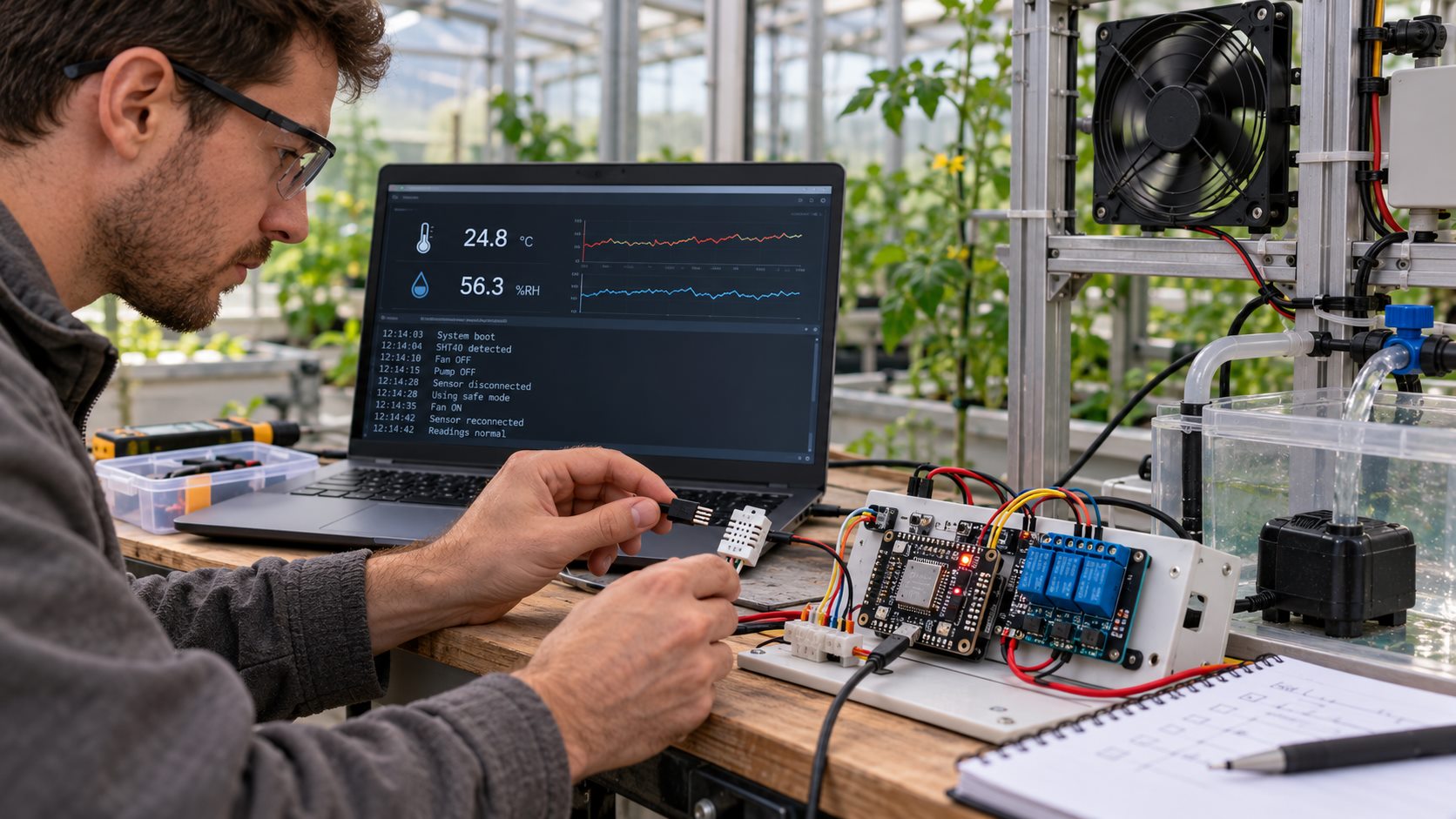
| Sensor disconnection | Disconnect SDA or SCL on the low-voltage side | After consecutive failures, disable spraying and enter the fail-safe state |
| High humidity | Apply a controlled humidity source; avoid direct droplets at the opening | After trigger conditions are met, execute no more than one heater cycle and complete cooldown |
| Spray interlock | Issue the test spray command | Do not run the heater or update mist-contaminated readings during spraying |
| Power-cycle recovery | Disconnect and restore low-voltage power under safe conditions | All relays initially remain off; system recovers automatically |
| Electromagnetic interference | Switch a fan or pump under electrically isolated test conditions | ESP32 does not reset; I²C error rate remains within acceptable limits |
Troubleshooting Guide
| Symptom or Error | Initial Checks | Recommended Action |
|---|---|---|
| Failed to connect to ESP32 | Bootloader/download mode, data-capable USB cable, port, board selection | Hold BOOT during “Connecting” until programming starts; use a known data-capable USB cable |
| Serial port not found | USB-to-UART driver and port ownership | Verify CP210x, CH34x, or onboard USB drivers; close other serial-monitor applications |
| Adafruit_SHT4x.h not found | Library and dependency installation | Install Adafruit SHT4x through Library Manager and accept all dependencies |
| I²C address 0x44 not detected | Voltage, SDA, SCL, pull-ups, and solder joints | Run an I²C scanner; lower the bus clock to 100 kHz and shorten the cable |
| Garbled serial output | Serial Monitor baud rate | Match Serial.begin(); this example uses 115200 baud |
| Humidity remains near 100 %RH | Condensation, water droplets, contamination, and placement | Improve protection and airflow first; then use limited heater recovery |
| Abnormal measurements after heating | NO_HEATER restoration and cooldown | Discard heated measurements; sample again only after cooldown |
| ESP32 resets when fan starts | Supply droop, ground loops, EMI, and relay driver | Separate supply branches, improve decoupling, suppression, and routing |
| Watchdog compilation errors | ESP32 Arduino Core version | Adapt to the official API for that version; do not mix Core 2.x and 3.x examples |
Optional: Network and Watchdog Enhancements
The reference sketch above runs locally; it does not implement Wi-Fi or a Task Watchdog. If you add remote monitoring, keep those services outside the control path.
Keep control running when Wi-Fi fails
Sensor acquisition, fan hysteresis and spray interlocks must continue during an outage. A failed connection or upload should return control to loop() promptly.
- Set finite connection and request timeouts shorter than the watchdog window.
- On failure, retain data in a bounded buffer or record the current state; send it when connectivity returns.
- Never wait indefinitely for Wi-Fi inside
loop().
Configure the watchdog for the installed core
ESP32 Arduino Core 2.x and 3.x bundle different ESP-IDF versions. Check the installed board-package version and follow its Task Watchdog API.
- Set the timeout beyond the longest normal blocking interval, including a heated read, network timeout and flash operation.
- Feed the watchdog only after the main loop completes its critical work. A separate timer that feeds it unconditionally can hide a stalled control loop.
Before commissioning
- Set every actuator to its safe output level before starting sensors or Wi-Fi.
- Log reset cause, last operating state and fault count to distinguish brownouts, watchdog resets and software faults.
- Test watchdog recovery with controlled firmware and live pumps or heaters disconnected.
Recommended Deployment Bill of Materials
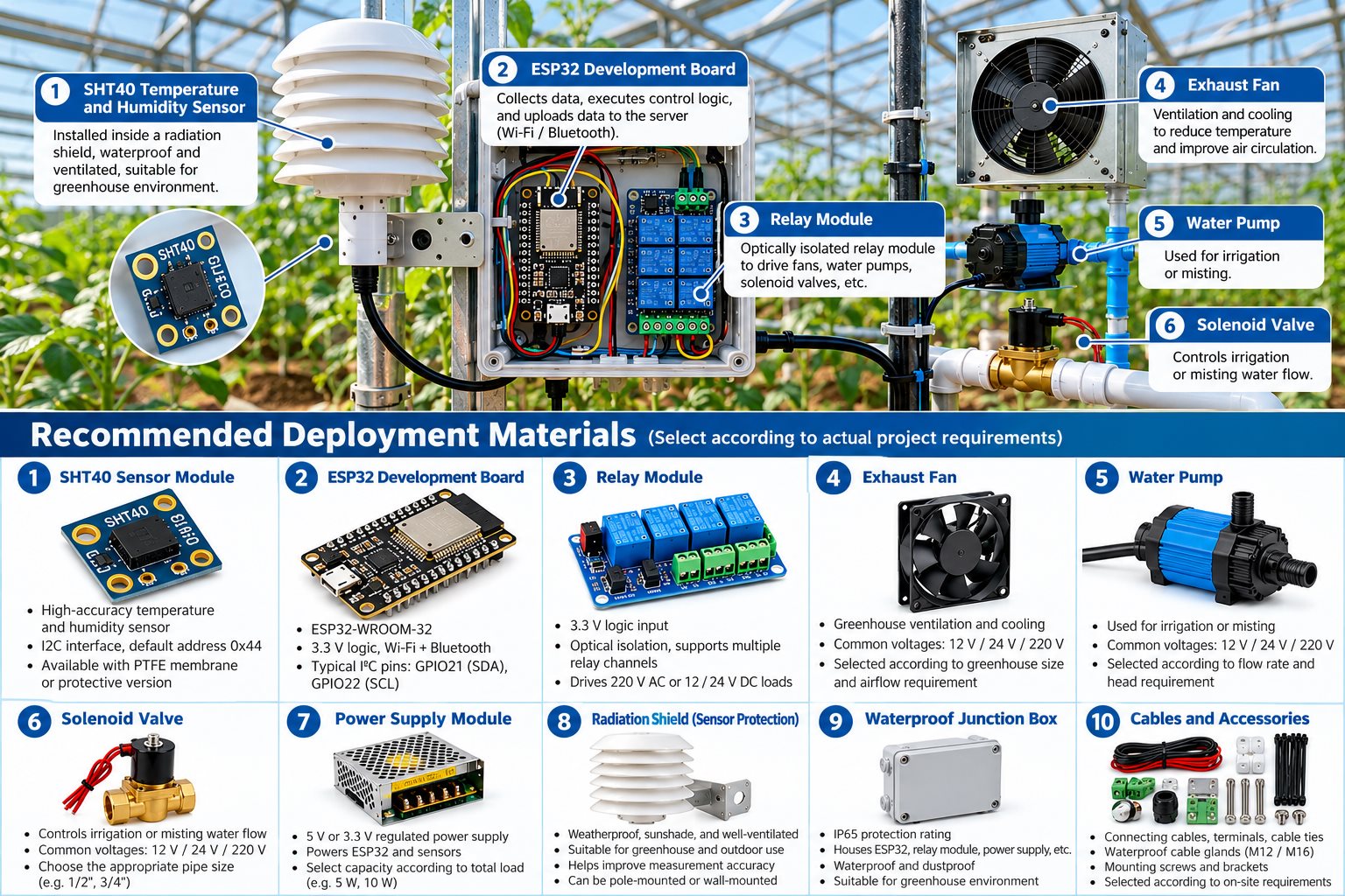
| Category | Recommended Component | Selection Criteria |
|---|---|---|
| Controller | ESP32 development board | 3.3 V logic, reliable USB interface, sufficient available GPIO pins |
| Sensor | SHT40 module or documented protected variant | Specified supply range, pull-up arrangement, and protection design |
| Enclosure | IP65-rated or higher electrical enclosure | Environmental sealing, protected terminals, thermal management, service clearance |
| Probe protection | Radiation shield, breathable membrane, probe housing | Airflow, drainage, serviceability, and low solar-radiation error |
| Cable entry | M12 or M16 waterproof cable gland | Select for cable diameter; provide drip loops |
| Drive stage | 3.3 V-compatible isolated driver or industrial relay | Contact rating, inrush capability, default state, documented isolation |
| Power supply | Compliant DC supply with separate regulated branches | Peak-current margin, fuse protection, surge suppression |
| Wiring | Shielded cable, twisted pair, terminals, cable ducts | Separate signal and power wiring; clear identification and service access |
Pre-Deployment Checklist
| Check | Pass condition |
|---|---|
| Power and I²C | Sensor and module supply are verified; SDA/SCL pull-ups and bus speed suit the installed wiring. |
| Placement | Sensor is shaded, ventilated and protected from spray; recovery after mist or heater use is measured. |
| Actuators | Relay polarity and default state match firmware; qualified personnel verify protection for the actual loads. |
| Control logic | Fan hysteresis is tested; irrigation has an independent trigger; heater readings are excluded through cooldown. |
| Fault handling | Sensor loss, network loss and restart tests enter the defined safe state; stale readings are rejected. |
| Logging | Logs include timestamps, sensor status, actuator states and reset causes; watchdog configuration matches the installed core. |
Technical sources
Scope and limitations
Set thresholds, heater intervals and cooldown times through on-site testing; the 5-second example is not a confirmed recovery time. For mains-powered or unattended equipment, use qualified electrical protection and hardware interlocks. Firmware safeguards alone are not a safety system.
Start with the basic ESP32–SHT40 readout if I²C acquisition is not yet stable. For unexplained offsets, see the accuracy guide; for heater effects, see heater diagnostics.
Evaluate the complete sensor assembly
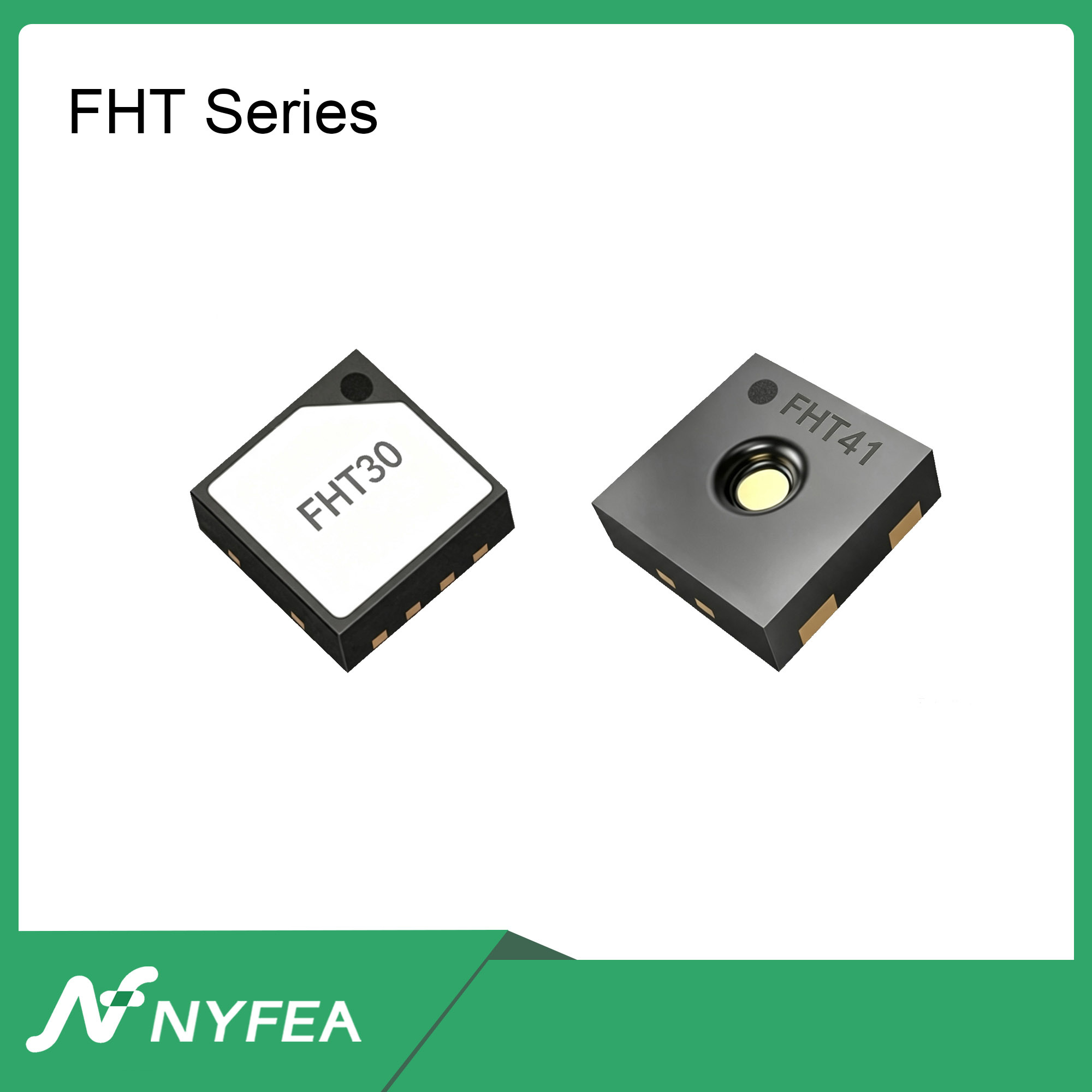
NYFEA FHT40 is an independent temperature and humidity sensor candidate for new greenhouse designs. Compare the exact device datasheet, interface, package, protective housing and environmental test results before considering it for this controller.
Review NYFEA FHT40Browse humidity sensorsSHT40 and SHT4x are Sensirion identifiers. NYFEA and FHT40 are independent products and are not affiliated with or endorsed by Sensirion. Illustrative images on this page are not installation records or performance evidence.